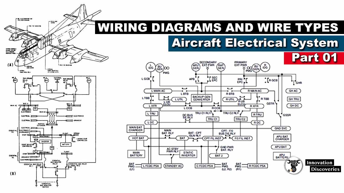
Wiring Diagrams and Wire Types – Aircraft Electrical System | Part 01
The satisfactory performance of any modern aircraft depends to a very great
Degree in the continuing reliability of electrical systems and subsystems. Improperly or carelessly maintained wiring can be a source of both immediate and potential danger. The continued proper performance of electrical systems depends on the knowledge and
Techniques of the technician who installs,
Inspects, and maintains the electrical system wires and cables.
Procedures and practices outlined in this section are general recommendations and
Are not intended to replace the manufacturer’s instructions and approved practices.
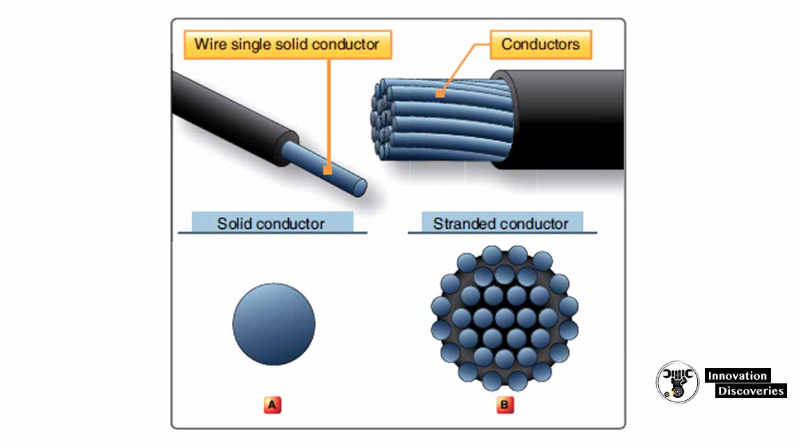
A wire is described as a single,
Solid conductor, or as a stranded conductor covered with an insulating material.
Figure 4 illustrates these two definitions of a wire.
Because of in-flight vibration and flexing, conductor round wire should be
Stranded to minimize fatigue breakage.
The term “cable,” as used in aircraft electrical installations, includes:
- Two or more separately insulated conductors in the same jacket.
- Two or more separately insulated conductors twisted together (twisted pair).
- One or more insulated conductors covered with a metallic braided shield (shielded cable).
- A single insulated center conductor with a metallic braided outer conductor (radio frequency cable).
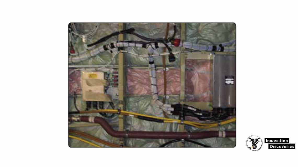
The term “wire harness” is used when an array of insulated conductors are bound
Together by lacing cord, metal bands,
Or other binding in an arrangement suitable for use only in specific equipment for
Which the harness was designed; it may include terminations. Wire harnesses are extensively used in aircraft to connect all the electrical components. [Figure 5]
For many years, the standard wire in light aircraft has been MIL-W-5086A,
Which uses a tin-coated copper conductor rated at 600 volts and temperatures of 105 °C. This basic wire is then coated with various insulating coatings. Commercial and military aircraft use wire that is manufactured under MIL-W-22759 specification,
Which complies with current military and FAA requirements.
The most important consideration in the selection of
Aircraft wire is properly matching the wire’s construction to the application environment. Wire construction that is suitable for the most severe environmental condition to be
Encountered should be selected. Wires are typically categorized as being suitable for either open wiring or;
Protected wiring application. The wire temperature rating is typically a measure of the insulation’s
Ability to withstand the combination of ambient temperature and
Current-related conductor temperature rise.
Conductor
The two most generally used conductors are copper and aluminum. Each has characteristics that make its use advantageous under certain circumstances. Also, each has certain disadvantages. Copper has a higher conductivity; is more ductile;
It has relatively high tensile strength and can be easily soldered. Copper is more expensive and heavier than aluminum. Although aluminum has only about 60 percent of the conductivity of copper, it is used extensively.
Its lightness makes possible long spans,
And its relatively large diameter for a given conductivity reduces corona
(The discharge of electricity from the wire when it has a high potential). The discharge is greater when a small diameter wire is used than when a large-diameter wire is used.
Some bus bars are made of aluminum instead of copper
Where there is a greater radiating surface for the same conductance. The characteristics of copper and aluminum are compared in Figure 6.
| Characteristic | Copper | Aluminum |
| Tensile strength (lb-in) | 55,000 | 25,000 |
| Tensile strength for same conductivity (lb) | 55,000 | 40,000 |
| Weight for same conductivity (lb) | 100 | 48 |
| Cross-section for same conductivity (CM) | 100 | 160 |
| Specific resistance (ohm/mil ft) | 10.6 | 17 |
Figure 6. Aircraft electrical cable
Plating
Bare copper develops a surface oxide coating at a rate dependent on temperature. This oxide film is a poor conductor of electricity and inhibits the determination of wire. Therefore, all aircraft wiring has a coating of tin, silver, or nickel that has far slower oxidation rates.
- Tin-coated copper is a very common plating material. Its ability to be successfully soldered without highly active fluxes diminishes rapidly with time after manufacture. It can be used up to the limiting temperature of 150 °C.
- Silver-coated wire is used where temperatures do not exceed 200 °C (392 °F).
- Nickel-coated wire retains its properties beyond 260 °C, but most aircraft wire using such coated strands has insulation systems that cannot exceed that temperature on long-term exposure. Soldered terminations of nickel-plated conductor require the use of different solder sleeves or flux than those used with tin- or silver-plated conductor.
Insulation
Two fundamental properties of insulation materials are insulation resistance and dielectric strength. These are entirely different and distinct properties.
Insulation resistance is the resistance to current leakage through and over the surface of insulation materials. Insulation resistance can be measured with a
Megohmmeter/insulation tester without damaging the insulation,
And data so obtained serves as a useful guide in determining the general condition of the insulation. However, the data obtained in this manner may not give a true picture of the condition of the insulation. Clean, dry insulation having cracks or other faults might
Show a high value of insulation resistance but would not be suitable for use.
Dielectric strength is the ability of the insulator to withstand potential difference and is usually expressed in terms of the voltage at which the insulation fails because of the electrostatic stress. Maximum dielectric strength values can be measured by raising the
Voltage of a test sample until the insulation breaks down.
The type of conductor insulation material varies with the type of installation. Characteristics should be chosen based on the environment, such as abrasion resistance,
Arc resistance, corrosion resistance, cut-through strength, dielectric strength,
Flame resistant, mechanical strength, smoke emission, fluid resistance,
And heat distortion. Such types of insulation materials (e.g., PVC/nylon, Kapton®, and Teflon®) are no longer used for new aircraft designs, but might still be installed on older aircraft. Insulation materials for new aircraft designs are made of Tefzel®,
Teflon®/Kapton®/Teflon® and PTFE/Polyimide/PTFE. The development of better and safer insulation materials is ongoing.
Since electrical wire may be installed in areas where inspection is infrequent over extended periods,
It is necessary to give special consideration to heat-aging characteristics in the selection of wire.
Resistance to heat is of primary importance in the selection of wire for aircraft use,
As it is the basic factor in wire rating. Where wire may be required to operate at higher temperatures due either to high ambient temperatures,
High current loading,
Or a combination of the two, selection should be made based on satisfactory performance under the most severe operating conditions.
Wire Shielding
With the increase in the number of highly sensitive electronic devices found on modern aircraft,
It has become very important to ensure proper shielding for many electric circuits. Shielding is the process of applying a metallic covering to wiring and equipment to
Eliminate electromagnetic interference (EMI).
EMI is caused when electromagnetic fields (radio waves)
Induce high frequency (HF) voltages in a wire or component. The induced voltage can cause system inaccuracies or even failure.
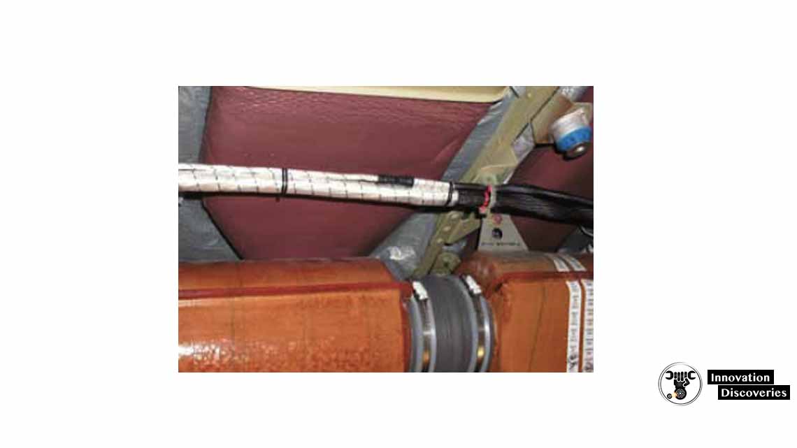
The use of shielding with 85 percent coverage or greater is recommended.
Coaxial, triaxial, twin axial, or quad axial cables should be used,
Wherever appropriate, with their shields connected to ground at a single point
Or multiple points, depending upon the purpose of the shielding. [Figure 7] The airframe grounded structure may also be used as an EMI shield.
Wire Substitutions
When a replacement wire is required in the repair and modification of existing aircraft,
The maintenance manual for that aircraft must first be reviewed to determine if;
The original aircraft manufacturer (OAM) has approved any substitution. If not, then the manufacturer must be contacted for an acceptable replacement.
wheeled Severe Wind and Moisture Problem (SWAMP)
SWAMP areas differ from aircraft to aircraft but are usually wheel wells,
Near wing flaps, wing folds, pylons,
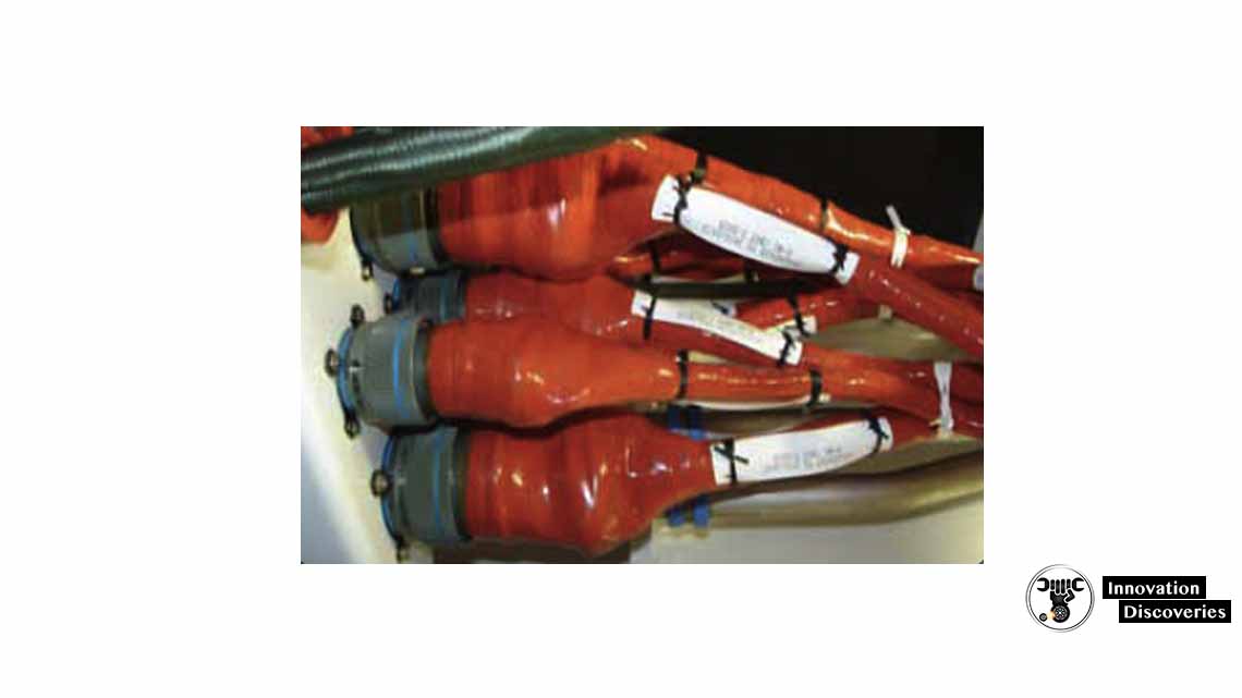
And other exterior areas that may have a harsh environment. Wires in these areas have often an exterior jacket to protect them from the environment. Wires for these applications often have design features incorporated into their construction
That may make the wire unique;
Therefore, an acceptable substitution may be difficult, if not impossible, to find.
It is very important to use the wire type recommended in the aircraft manufacturer’s maintenance handbook. Insulation or jacketing varies according to the environment. [Figure 8]
Aviation job
Also, read:
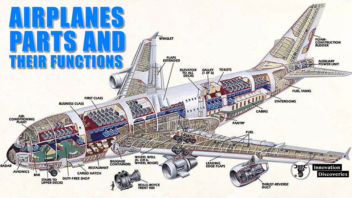
- AIRPLANES: PARTS AND THEIR FUNCTIONS
- How Do Airplanes Fly? Components
- If all the aircraft’s engines fail, will the plane still fly or will it fall out of the sky?
- How A Helicopter Fly And Constructed?
- How does a jet engine work?
3 Comments