Jet engines generate thrust by harnessing the principles of jet propulsion, expelling large volumes of fluid in one direction to propel a vehicle in the opposite direction. In aircraft, this forward motion creates a flow of air over the wings that produce lift to keep the airplane in the sky.
The thrust generation is accomplished by exploiting Newton’s third law of motion, which states that for every action there is an equal and opposite reaction. As air and combustion gases are forced out of an engine, they exert a corresponding force back on the engine, pushing the aircraft forward. In this way, jet engines are a type of reaction engine.
The term jet engine encompasses a variety of propulsive devices. From ramjets to turbofans, each jet engine design converts energy to propulsive power in different ways.
Turbojet
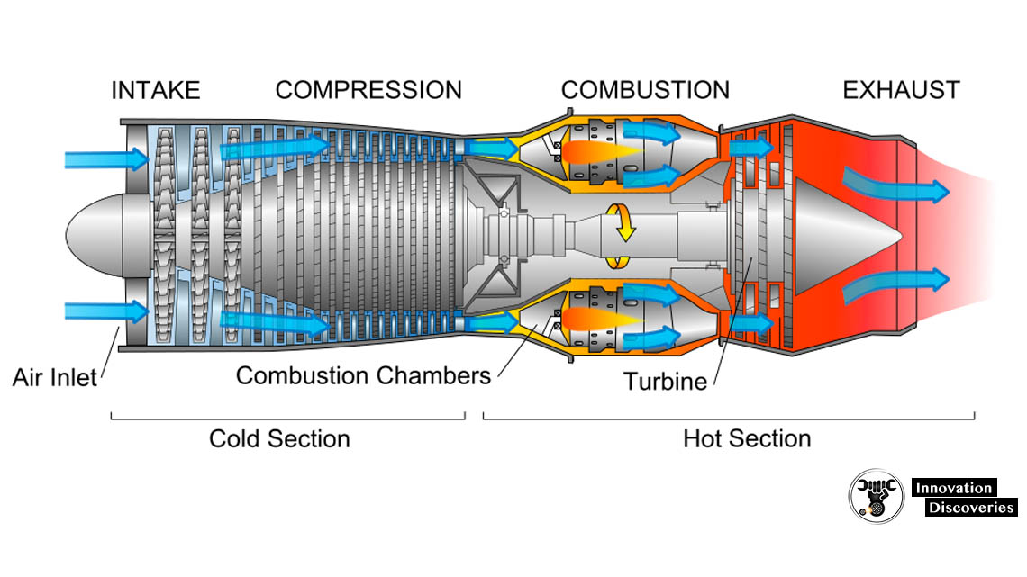
A typical type of jet engine known as a turbojet ingests air from the atmosphere, compresses and heats it, and allows it to exit at high velocities. Fuel is fed to the engine from the fuel tank by a low-pressure booster pump. Before entering the combustion chamber, fuel pressure is further increased by a two-stage main fuel pump to achieve adequate pressure for nozzle spray atomization. A portion of the pressurized fuel is sometimes utilized for purposes other than combustion, such as in fueldraulics fluid power systems that actuate variable compressor geometry, bleed air valves and turbine cooling valves.
The combustion products are channeled through a turbine section made up of several more stages of spinning-blade discs. The turbine extracts energy from the hot gases to power the compressor, to which it is connected by a shaft. Finally, the gas exits the engine through a converging nozzle at the rear, decreasing in pressure as it gains velocity. Turbojets are gas turbine engines, which are also used as power plants to generate electricity in industrial applications.
Turbofan
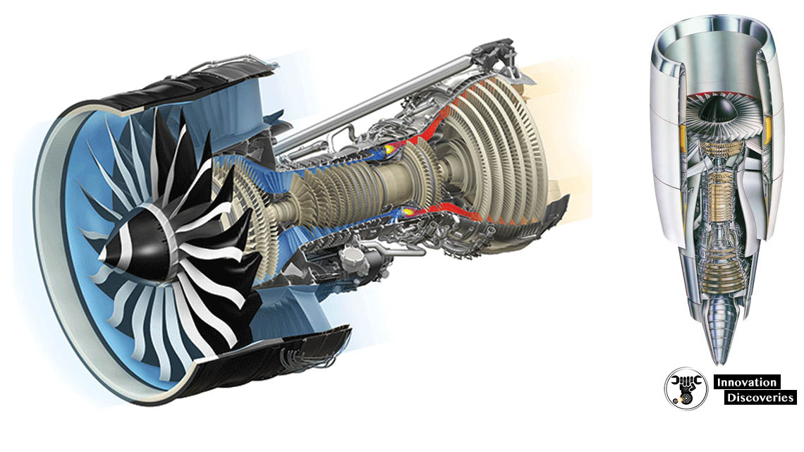
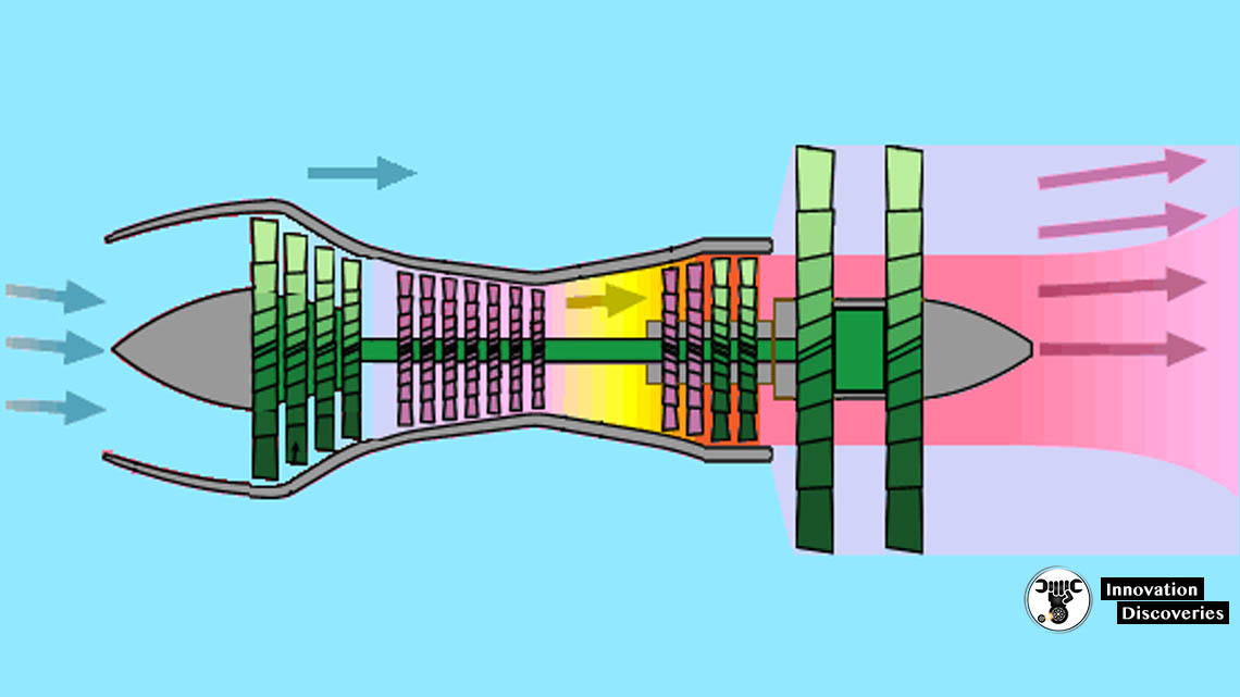
Modern commercial passenger aircraft are equipped with jet engines known as turbofans. Some of this air is directed into the compressor, but most of it is transported around the core gas turbine to the rear of the engine. Turbofans derive a majority of their thrust from this bypass flow of air. The large volume of air moving at slower velocities creates less noise than a turbojet and results in more fuel-efficient operation.
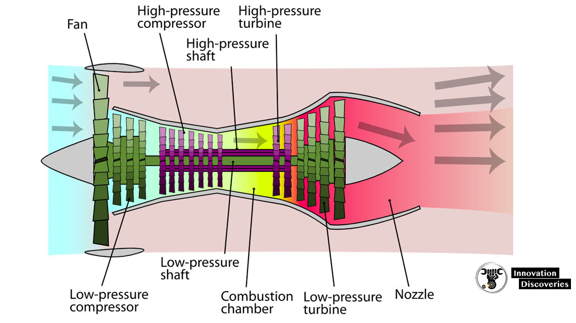
Turbofan engines have better overall fuel efficiency than turbojets at the cost of increased mechanical complexity. In addition to the core compressor, turbine and shaft, the fan is powered by another shaft connected to an additional turbine. In many advanced engines, the compressor-turbine sections are split into low- and high-pressure segments. In these configurations, the low-pressure compressor and low-pressure turbine are connected by a shaft and spin as one «spool,» separate from the high-pressure compressor and high-pressure turbine spool.
Each spool spins independently on shafts arranged in a concentric configuration, nested within each other and running axially along the engine’s length. This configuration allows each spool to function at its optimal operating point, improving engine efficiency.
Other types
Other types of jet engines include turboprops, turboshafts, propfans, and ramjets.
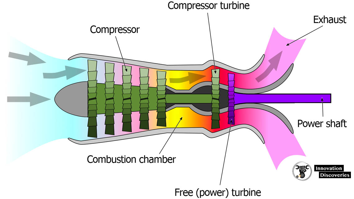
Turboprops consist of a propeller-driven by a turbojet-type engine. Unlike turbojets, turboprops extract more energy from combustion gases in the turbine section to transmit almost all of their power to a shaft that drives the propeller instead of generating high-thrust exhaust.
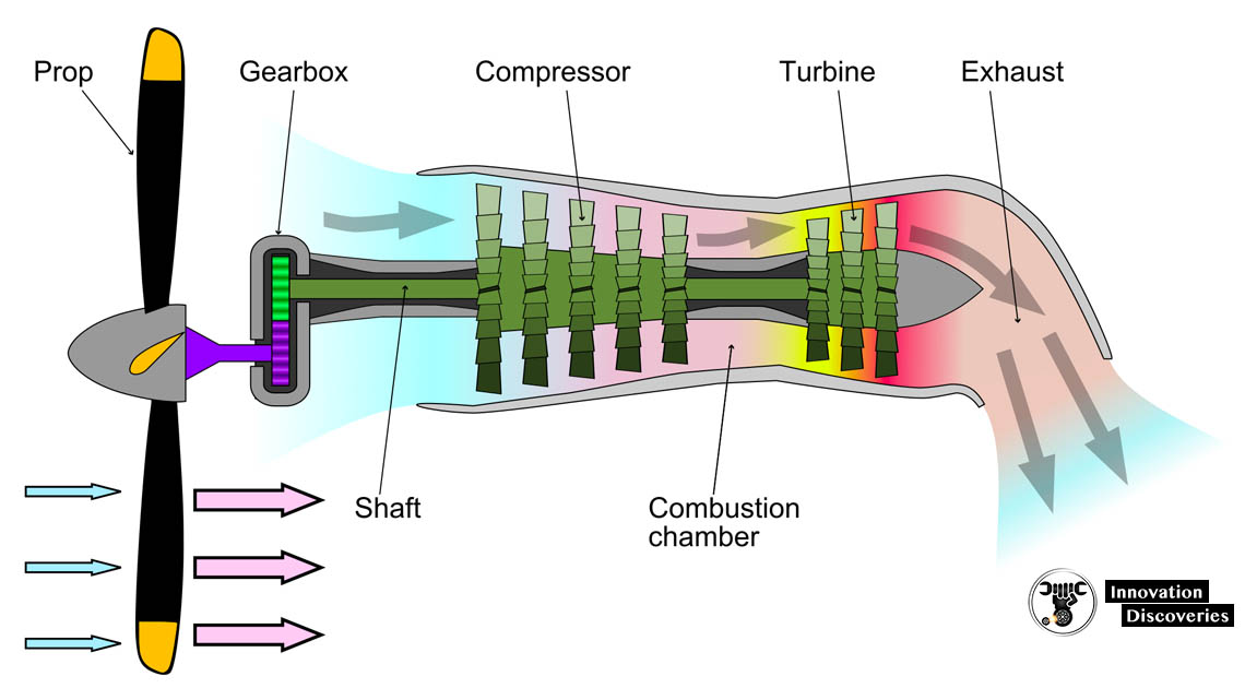
Turboshafts are similar to turboprops in that they employ a turbojet-type engine to drive a shaft. Instead of direct shaft attachment to a propeller, however, turboprops drive transmissions in applications like helicopters, ships, and tanks.
Propfans,
Also known as open rotor engines, is similar to turboprops, but instead of typical propeller designs, propfans are equipped with a large number of specially-contoured blades mounted externally at the front, mid or rear of the nacelle, in some cases in a contra-rotating configuration consisting of two rotors rotating in opposite directions. Propfans offer high fuel efficiency but they produce more noise compared to designs that enclose the propeller or fan sections within a nacelle.
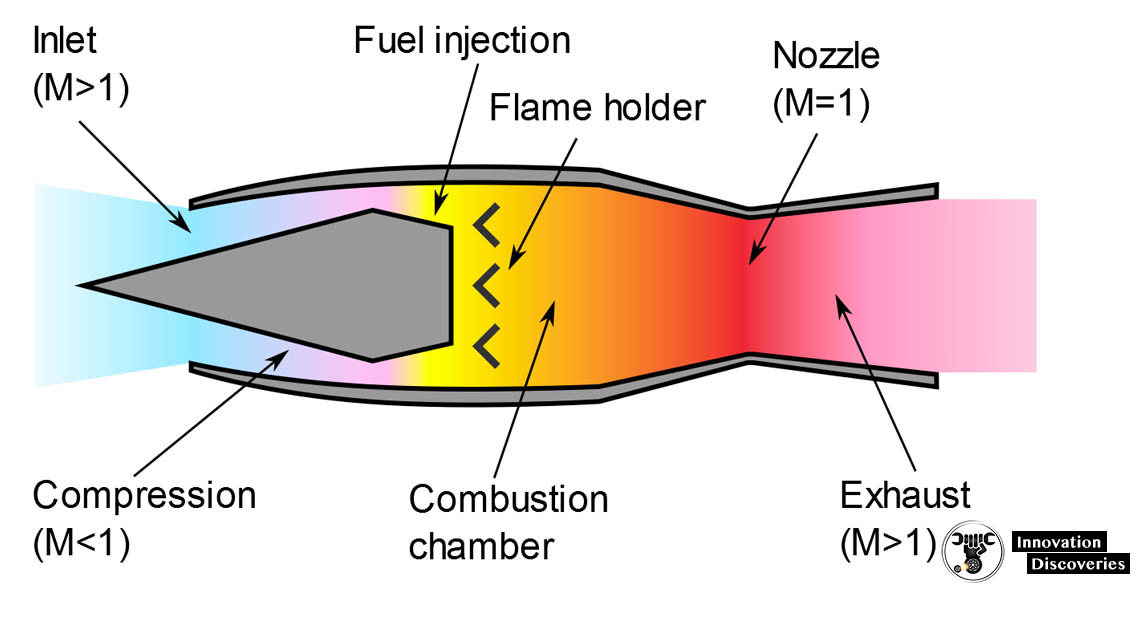
Ramjets are simple jet engines that lack the rotating machinery contained in turbojets. Instead of compressing air using spinning compressors powered by a turbine section, ramjets exploit the forward motion of the aircraft as a means to generate high-pressure air. Fuel is then injected into the flow, ignited and exhausted through the nozzle to produce thrust.
Ramjets generate no thrust without forwarding aircraft motion and very little thrust until the aircraft approaches the speed of sound, reaching peak efficiency at supersonic speeds around Mach 3. Scramjets are ramjets that carry out combustion in fuel/air mixtures flowing at supersonic speeds, allowing them to operate more efficiently at aircraft speeds above Mach 6.
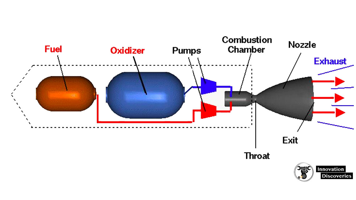
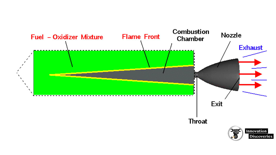
Rocket engines use jet propulsion to generate thrust by burning propellants and exhausting the combustion products through nozzles. Unlike jet engines that ingest atmospheric air to utilize its oxygen in the combustion reaction with fuel, rockets store both the oxidizer and fuel onboard, allowing them to operate in the vacuum of space in addition to Earth’s atmosphere. The propellants are stored in separate tanks in liquid-fuel rockets or as a fuel-oxidizer mixture known as a grain in solid rocket motors.
Turbofan example
To get a feel for typical working temperatures and pressures through the various stages of a jet engine, consider the figure below, which shows a cross-section of the Pratt and Whitney JT9D-7 high-bypass turbofan engine. The JT9D-7 powered the original Boeing 747 when it entered service in 1970. Variants of the engine also powered later versions of the 747 as well as the 767, Airbus A300, A310, and McDonnell Douglas DC-10.
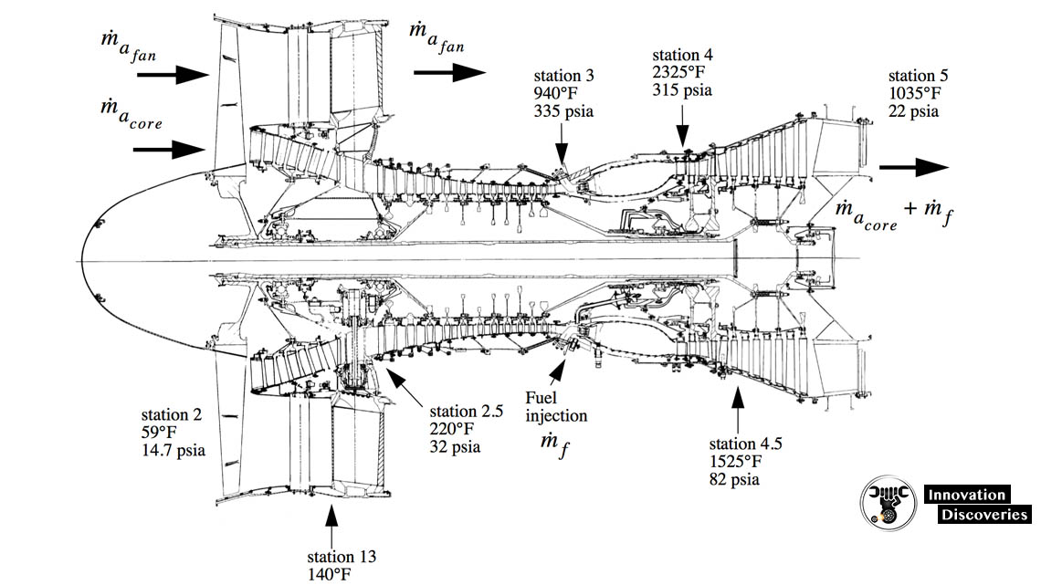
In the figure, typical temperatures and pressures are shown at various stations throughout the engine. Flow direction is indicated by arrows. ṁa,fan is the mass flow rate of bypass air through the fan, ṁa,core is the mass flow rate of air through the engine core and ṁf is the fuel mass flow rate.
Station 2 corresponds to freestream air at static sea-level conditions of 59° F and 14.7 psia.
Station 2.5 is located in the engine core after the low-pressure compressor and before the high-pressure compressor.
After passing through the inlet, fan and low-pressure compressor, core air has risen in temperature and pressure to 220° F and 32 psia.
Station 3 is located at the exit of the high-pressure compressor before the combustion chamber. Combustion has resulted in a spike in gas temperature to 2325° F. Pressure has decreased slightly to 315 psia.
Station 4.5 is located between the low-pressure turbine and the high-pressure turbine. The low-pressure turbine has extracted some of the flow’s energy at this point as the gas expands through it, falling in temperature and pressure to 1525° F and 82 psia.
Station 5 is located at the exit of the turbine, where gas has dropped to 1035° F and 22 psia.