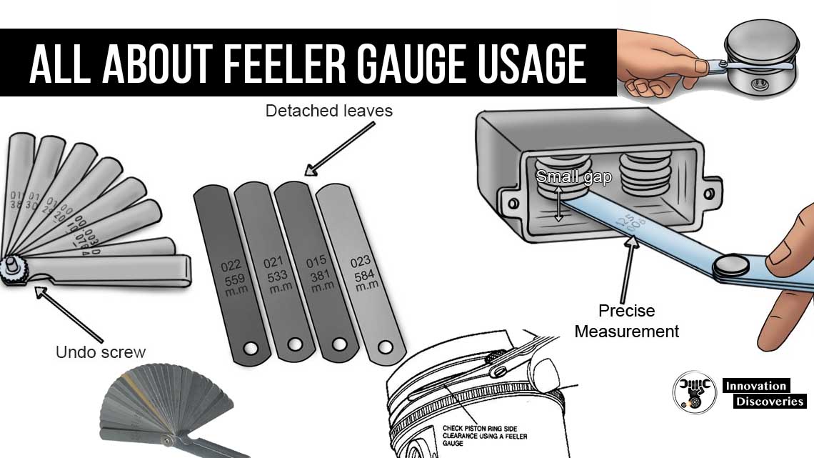
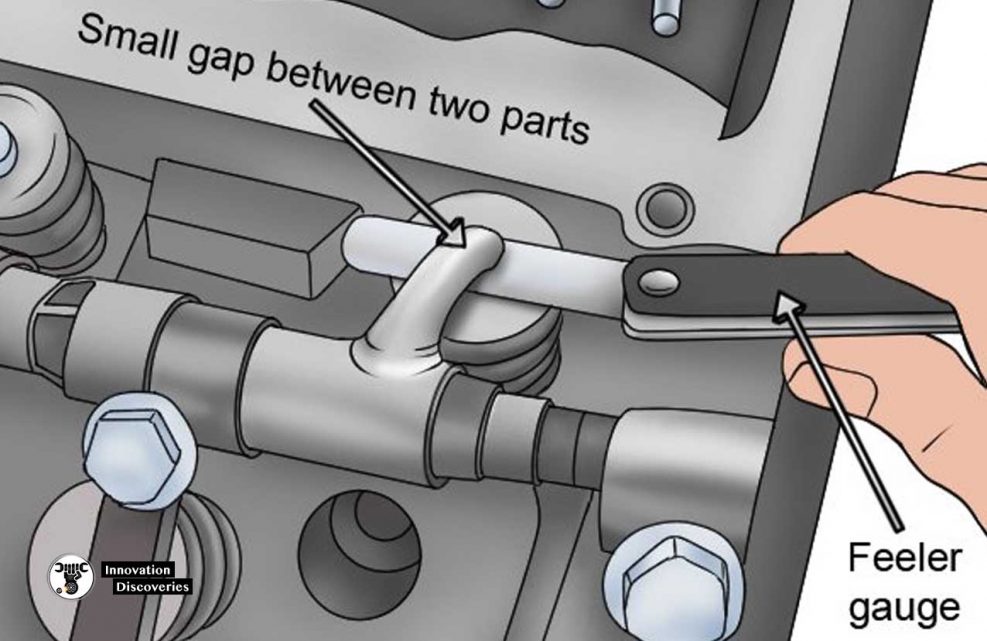
A feeler Gauge is a gauge used for measuring a set of very small gaps normally less than 1 mm between two parallel surfaces.
The thickest possible blade that can be inserted into a gap or crack shows its width. Both metric and imperial measurements are inscribed on each feeler gauge blade.
Feeler Gauge Usage
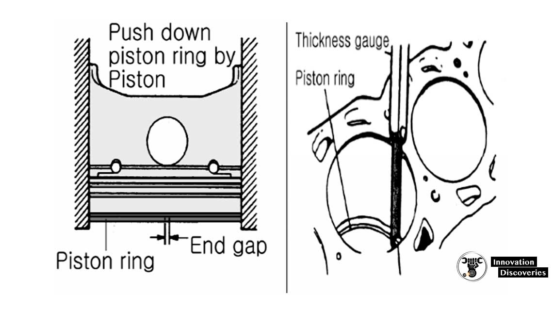
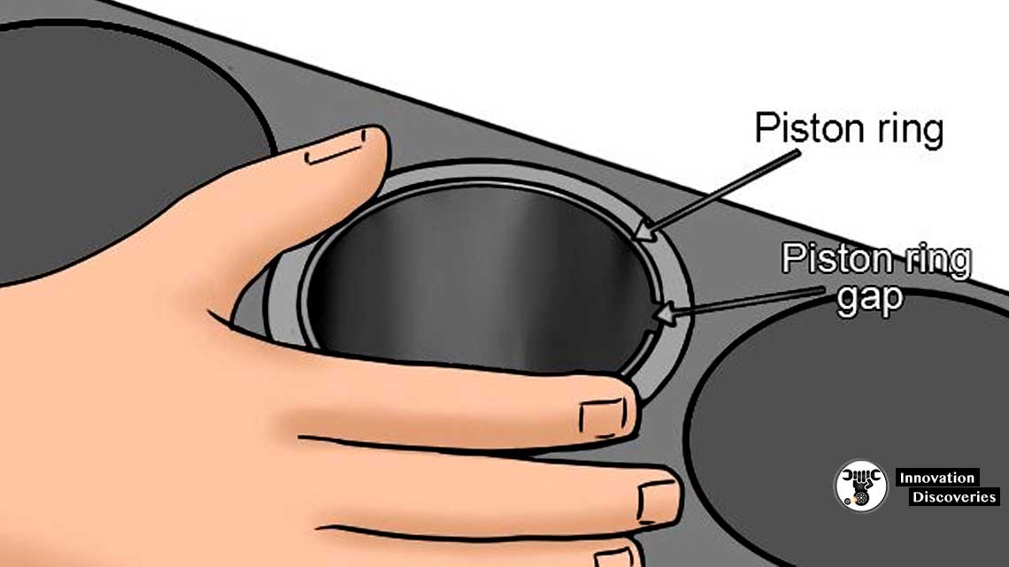
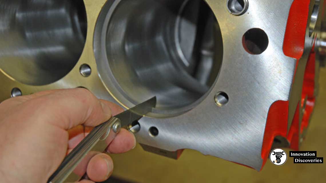
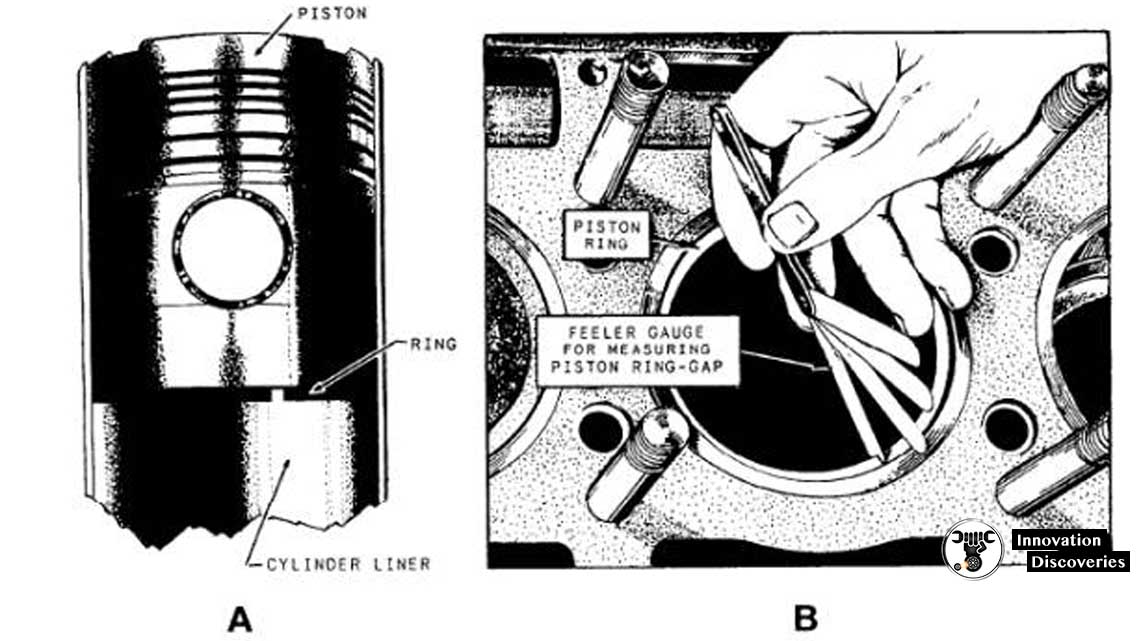
Feeler measuring of Piston Ring End Gap•Clean the cylinder walls.
•Insert the piston ring in the cylinder.
•Push the piston ring using a piston until the ring is reached to the piston pin boss.
•Take care, the end gap should not be located at the direction of the axis or perpendicular direction of the crankshaft.
•When the piston ring is inserted in the cylinder, the piston ring with facing the mark towards the cylinder head.
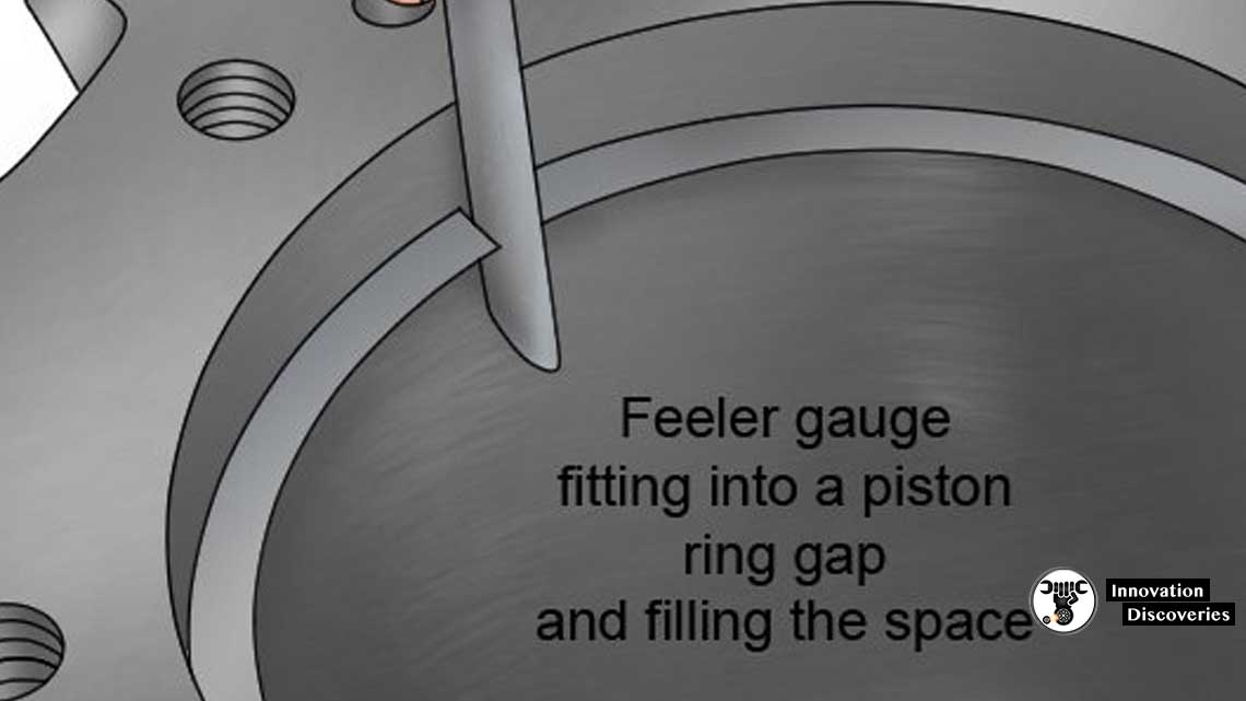
•Measure the piston ring end gap.
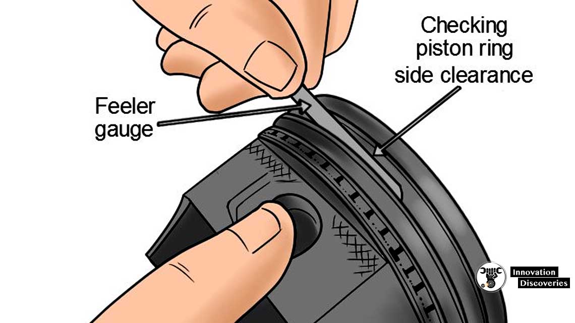
To measure PISTON RING LATERAL GAP
- Insert the feeler gauge until it reaches into the ring groove.
- Check at least at 3 -4 points.
To measure WARPAGE / DEFORMATION
- Remove and clean the foreign matters from the surface.
- Measure at the 7 positions using a straight edge and filler gauge as shown in the below picture.
- Measure the clearance between the cylinder head surface and the straight scale.
- Avoid the coolant passage and the oil passage.
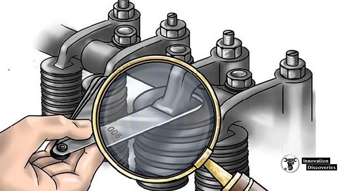
To measure Tappet Clearance Adjustment
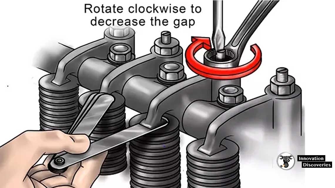
How To Check Tappet Clearance
1. Taking all safety precautions.
2. Make sure the piston is on TDC.
i. From the marking on the flywheel.
ii. From the fuel cam.
iii. Push rod should be free. (both the valve should be close at this stage ie at the end of compression stroke)
3. Make sure the engine has cooled down.
4. Loosen the lock nut of the rocker arm.
5. Now adjust the tappet clearance between the rocker arm & valve stem by tightening or loosing the nut below the lock nut.
6. Use a feeler gauge to adjust the suction valve clearance as .35mm an exhaust valve clearance as .45mm.

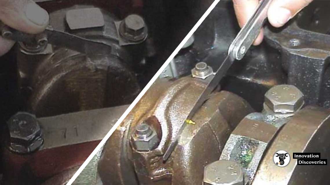
To measure Idler Gear End Clearance
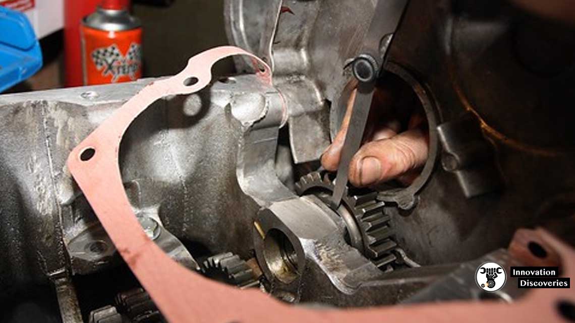
To measure Big End Bearing Clearance
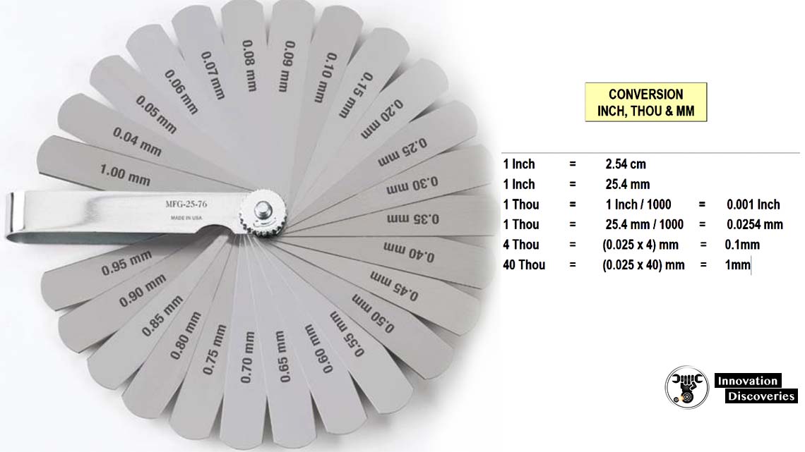
Feeler Gauge Sizes
The specific feeler gauge sizes included in a set depend on the number of blades in the set as well as whether the feeler gauge set is an English or metric size set.
A representative set of feeler gauge sizes for a decimal inch set is shown below in Group 1, and a decimal millimetre size set is shown in Group 2. These are based on a 25-blade count set – other blade combinations and sizes are available.
In actual use, it is often possible to stack together more than one blade to obtain a gauge for a size not included in the set.
For example, the 0.0015” and the 0.0020” sizes can be combined to provide a gauge reference for 0.0035”, which is not in the set of blades shown below in table 1.
Group 1 – Typical feeler gauge blade size chart for a 25-blade decimal inch gauge set
Blade Sizes (in Inches)
0.0015″
0.0020″
0.0030″
0.0040″
0.0050″
0.0060″
0.0070″
0.0080″
0.0090″
0.0100″
0.0110″
0.0120″
0.0130″
0.0140″
0.0150″
0.0160″
0.0170″
0.0180″
0.0190″
0.0200″
0.0210″
0.0250″
0.0270″
0.0300″
0.0400″
Group 2 – Typical feeler gauge blade size chart for a 25-blade decimal millimetre gauge set
Blade Sizes (in mm)
0.04 mm
0.05 mm
0.06 mm
0.07 mm
0.08 mm
0.09 mm
0.10 mm
0.15 mm
0.20 mm
0.25 mm
0.30 mm
0.35 mm
0.40 mm
0.45 mm
0.50 mm
0.55 mm
0.60 mm
0.65 mm
0.70 mm
0.75 mm
0.80 mm
0.85 mm
0.90 mm
0.95 mm
1.00 mm
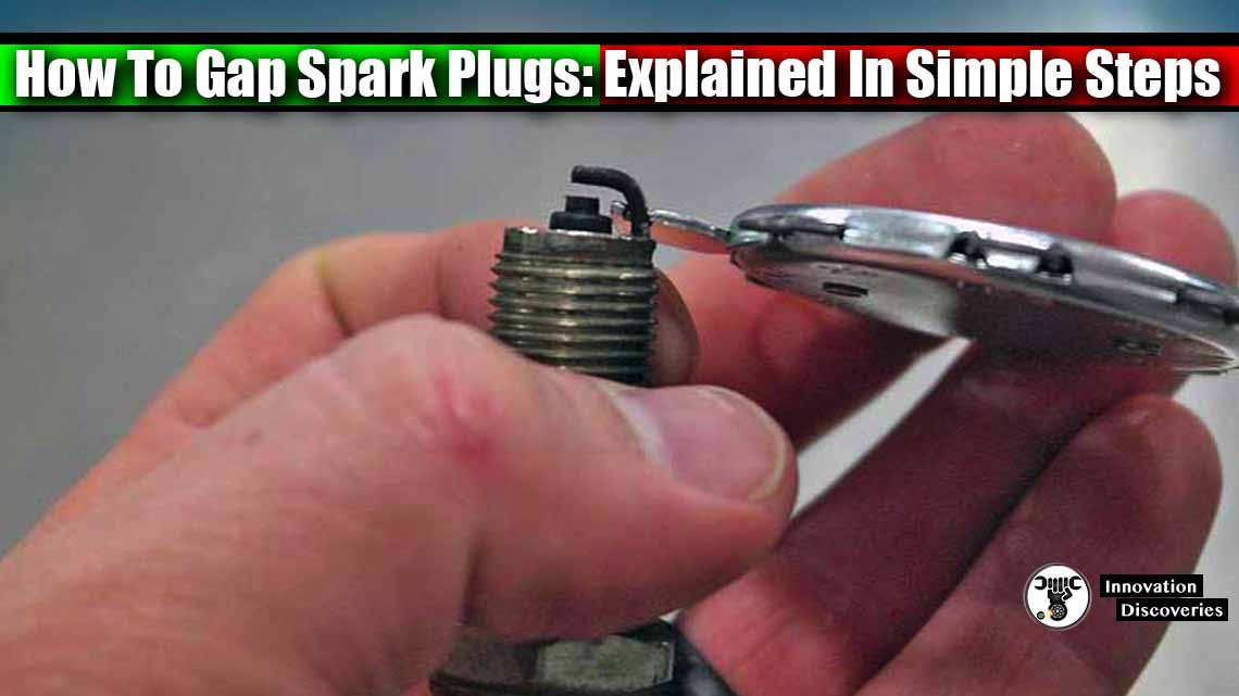
Read: HOW TO GAP SPARK PLUGS: EXPLAINED IN SIMPLE STEPS


One Comment