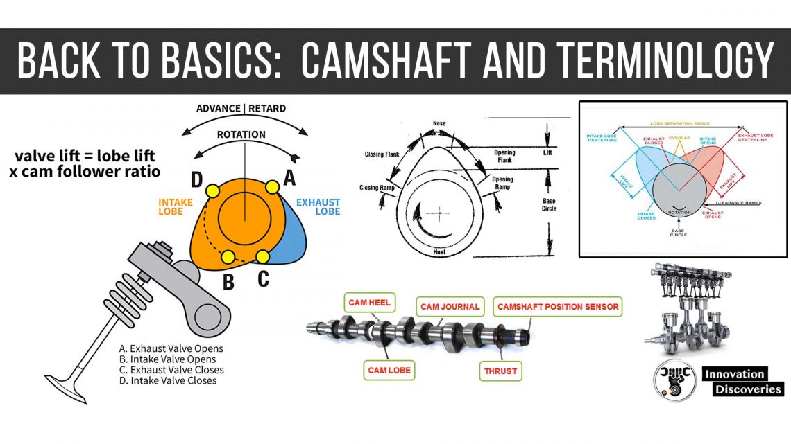
Camshaft Basics and Terminology
The Camshaft is the “heart” of the gasoline engine.
Your engine will not perform to its highest potential unless the cam is precision ground to provide performance at the speeds that you require.
Everything else in your engine may be performing tip-top, the carburetor and ignition systems for example.
Camshaft/Crankshaft Basics
Today the camshaft is sometimes called a “bump stick“, while old-time race drivers called it the “Jiggler stick“. It was just as mysterious then as it is to most of us today!
However, you are familiar with the strokes of the four-cycle engine, intake, compression, power, and exhaust.
Each stroke is one-half of a revolution or 180° of crank movement.
All four strokes (4 x 180° = 720° ) represent two complete revolutions of the crank.
The cam is connected by a 2-1 ratio sprocket or gears, so it only turns once to the crank’s two turns (Two crank degrees equal one cam degree).
When viewed from the front of the car, the crankshaft turns clockwise.
The camshaft also turns clockwise if connected via sprockets and chain. It turns counterclockwise when connected by gears.
The purpose of the cam is to operate the valves in the correct sequence in relation to piston movement.
You may get a copy of the spreadsheet to do simple camshaft calculations by clicking on the link below (angles, duration, lob separation, etc.).
Downloads
The following files can be downloaded by clicking on the link:
Degreeing Cam – Excel spreadsheet showing calculations to make when degreeing a cam profile.
Cam Spring – Excel spreadsheet showing how to perform simple force calculations.
This topic is divided into the following parts:
- terminology for angles and lift
- lobe terminology
- lift curves
Angle and Lift Terminology
There are several terms and abbreviations which are used when discussing camshafts.
The following abbreviations have to do with the location of the piston in the cycle.
- TC or TDC – Top Center or Top Dead Center (piston at the highest point)
- BC or BDC – Bottom Center (piston at lowest point)
- BTC or BTDC – Before Top Center (piston rising)
- ATC or ATDC – After Top Center (piston lowering)
- BBC or BBDC – Before Bottom Center (piston lowering)
- ABC or ABDC – After Bottom Center (piston rising)
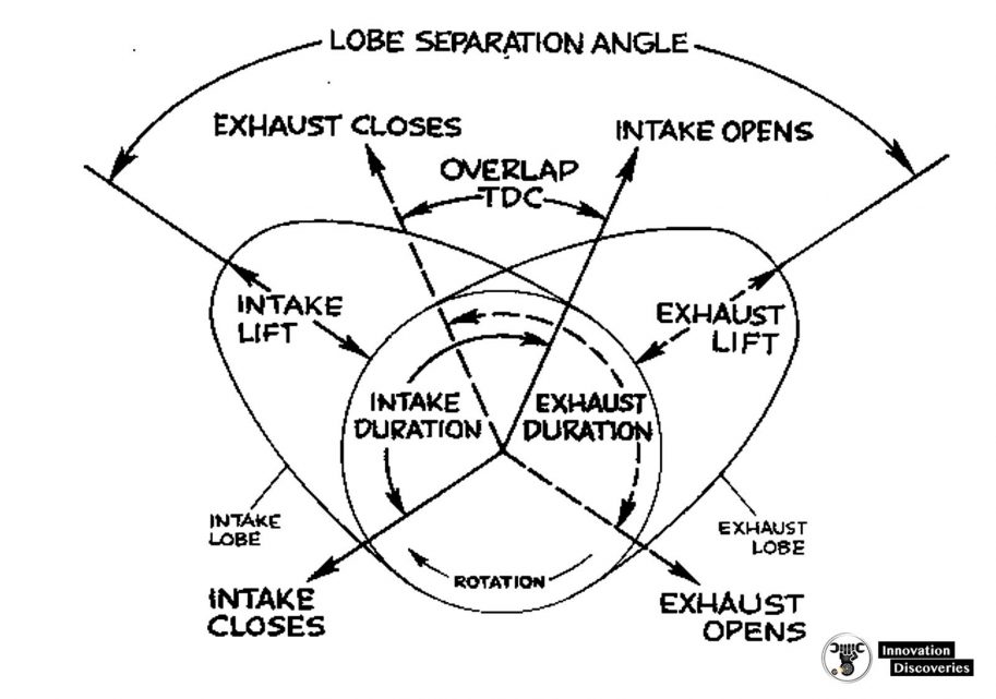
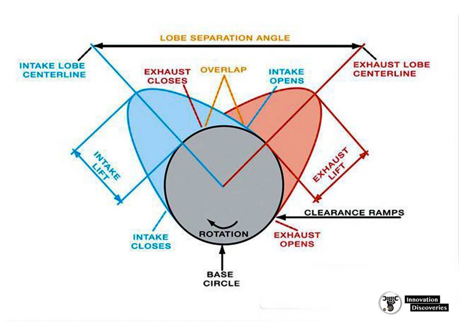
Some of the other terms used are illustrated in the drawing and are explained below.
Valve opening and Closing Angles
The angles (usually measured in crankshaft degrees) when the valves first leave and then return to their seats.
The opening and closing angles may also refer to a specified nominal lift, e.g. at 0.050 in cam lift.
For example, a cam’s timing may be stated as 25-65-65-25.
These numbers are (1) intake opening BTDC, intake closing ABDC, (3) exhaust opening BBDC, and (4) exhaust closing ATDC.
For these numbers to have meaning, the lift at which the numbers are taken must be specified.
Duration
The difference between the closing and opening angles. This is the number of degrees the valves is “off their seats”.
Duration is usually expressed in crankshaft degrees.
The duration may also refer to the number of degrees that the lift is greater than a specified value, e.g. duration at 0.050 lift.
For a cam with timing 25-65-65-25, the intake and exhaust duration are both (25 + 65 + 180) = 270 degrees.
Advertised Duration
A duration which is advertised without specifying the lift at which it was measured. These numbers are worthless.
Cam Lift
The lift is measured at the tappet or lifter. Gross lift is measured with no valve clearance, a Net lift is an actual lift with valve clearance.
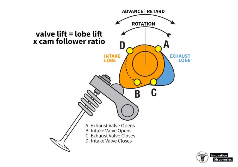
Valve Lift
The cam lift (gross or net) is multiplied by the rocker ratio.
Valve Clearance (Tappet Gap) or Valve Lash
The maximum space between the end of the valve stem and the adjacent rocker end or lifter.
The following shows some simple calculations that can be done easily using the cam calculator program on the link below.
Overlap
This is the number of degrees that the intake and exhaust valves are open at the same time.
A cam with timing of 25-65-65-25 has (25 + 25) = 50 degrees of overlap. Overlap is the most important parameter affecting idle and off idle quality.
A large overlap causes a rough or Lopey idle. Increasing the duration or decreasing the lobe separation causes an increase in the overlap.
Lobe Centerline
The highest lift point of a cam lobe is expressed in crankshaft degrees.
For the asymmetric lobe, the centerline is the average of the opening and closing angles.
Asymmetric cam with timing 25-65-65-25 has intake and exhaust centers of (65+180-25)/2 = 110 ATDC and 110 BTDC, respectively.
Lobe Separation Angle or Lobe Displacement Angle
The angle between the centerlines of intake and exhaust lobes is expressed in camshaft degrees.
For timing 25-65-65-25, the lobe separation is 110 cam degrees (220 crank degrees).
Cam Advance
The position of the midpoint between intake and exhaust lobes relative to TDC.
A cam with timing 25-65-65-25 has no advance and is said to be “straight-up”.
If the same cam is advanced 4 degrees, its timing becomes 29-61-69-21.
The intake and exhaust centerlines are now at 106 ATDC and 114 BTDC respectively.
Dual Pattern Cam
If the intake and exhaust lobes have a different grind, the cam is called a dual pattern cam or dual pattern grind.
From the earliest days of cam design, it has been common to use an exhaust lobe with 10 to 20 degrees more duration than the intake lobe.
A spreadsheet that performs the calculations to determine lobe centers, lobe separation, and advance is available for download.
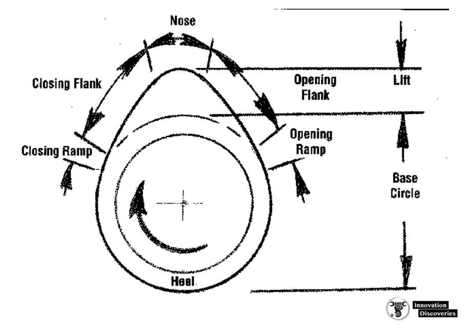
Lobe Terminology
Some of the terminology, which describes a single lobe is illustrated in the drawing below.
Lift Curves
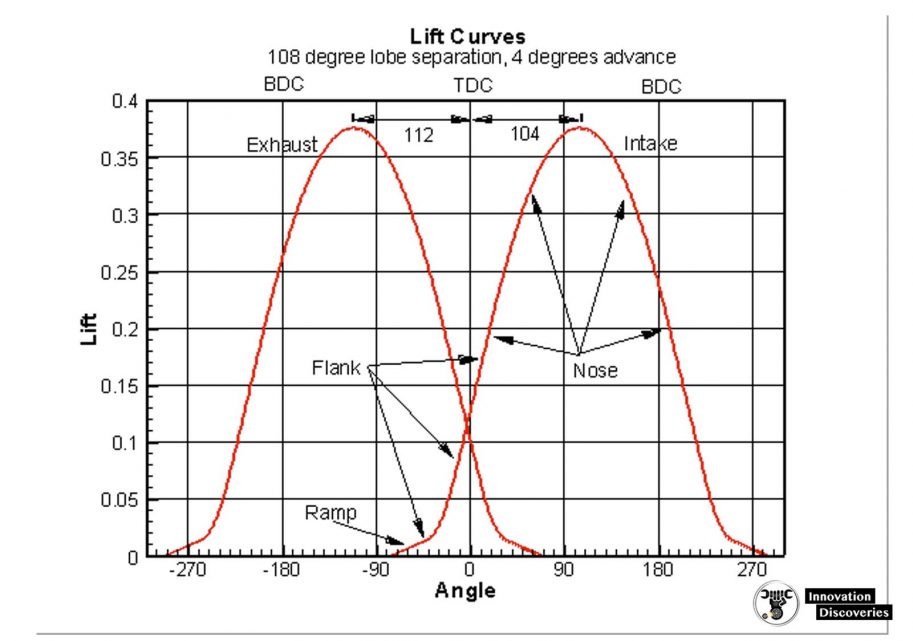
The purpose of the cam lobe is to raise the lifter and open the valve.
You can look at the lobe, but it doesn’t tell you exactly how it is going to do its job. The lift curve is a more precise way to look at the cam lift.
It is a graph of the lifter (or valve) motion as the cam rotates. Below is an example for a cam with 251 degrees of duration at 0.050 lift.
The lift curve can be measured using a degree wheel and dial indicator or more accurately using a computer-driven cam profiling system.
The opening intake ramp and flank and the intake nose are indicated on the graph. The ramp does not extend much beyond the valve opening, usually, less than 0.015 in (0.4 mm) lift.
After the ramp, the large upward curvature indicates the start of the flank. The nose portion is the large central area with negative curvature.
READ: Difference Between Crankshaft And Camshaft