Basics of Oil Hydraulics
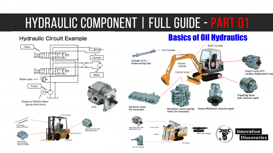
What is oil hydraulics?
Oil hydraulics refers to a group of devices or a system that drives a hydraulic pump with power sources, such as engines and electric motors, to transform mechanical energy to fluid energy in order to produce mechanical movement using an actuator like a cylinder while controlling energy output.
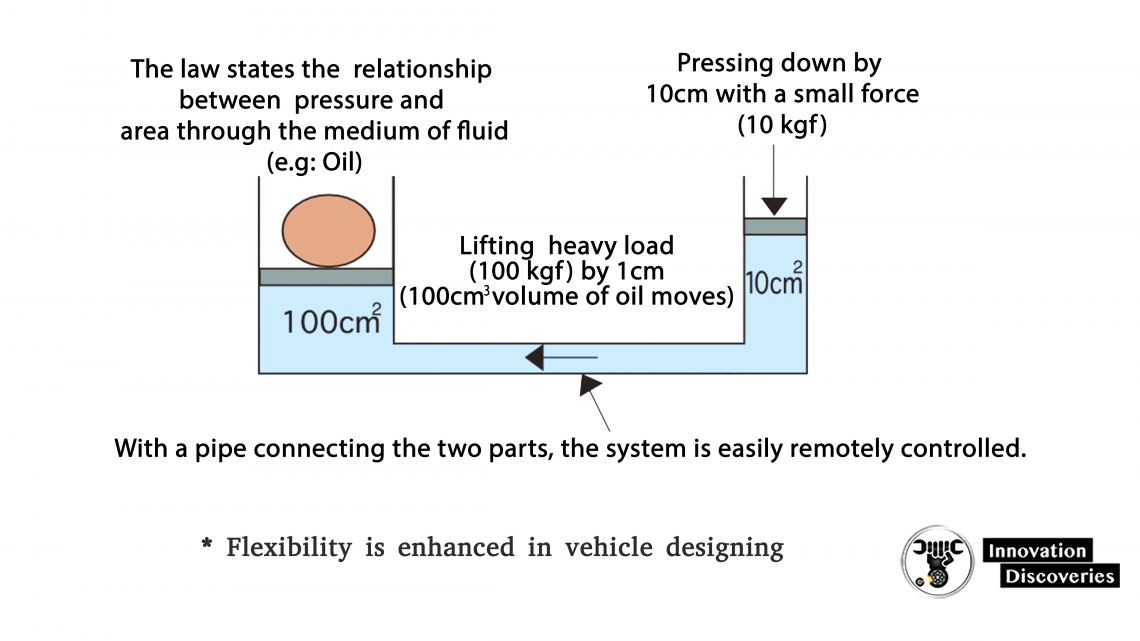
Pascal’s Law
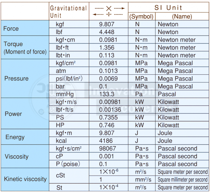
Unit Conversion Table
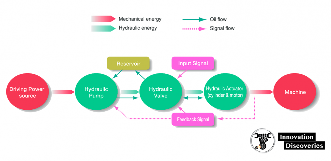
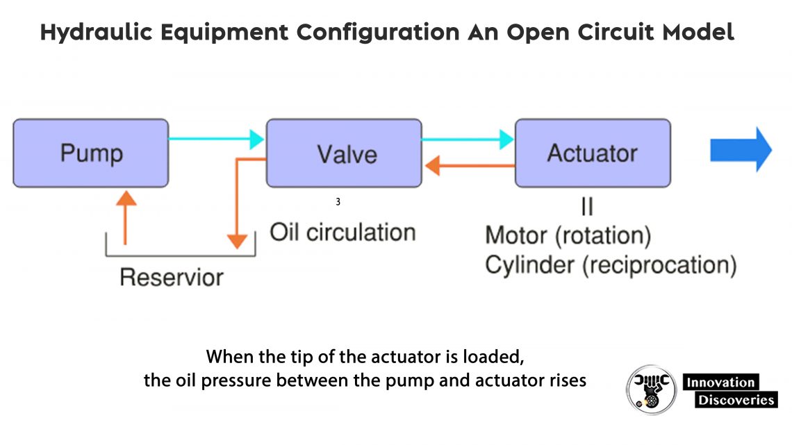
- In the hydraulic system, the (mechanical) power source rotates the hydraulic pump, by which the oil is drawn from the reservoir.
- The oil flows into the hydraulic actuator via the hydraulic valve.
- The actuator transmits generated power to the machine and activates it.
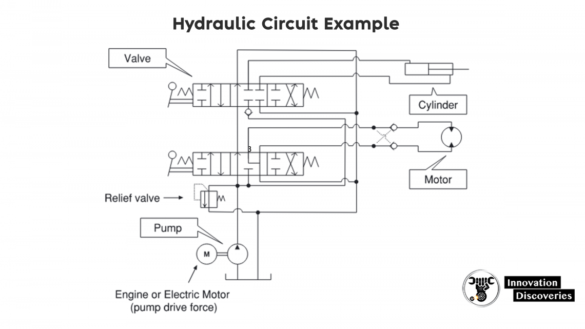
Basic Configuration of Hydraulic Circuit
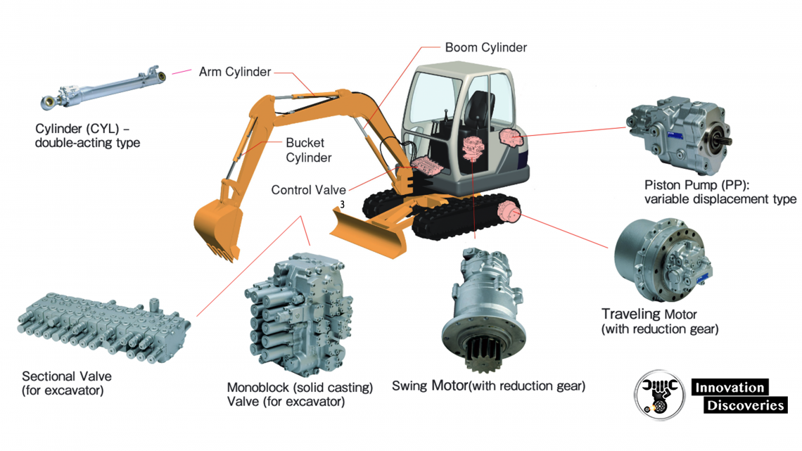
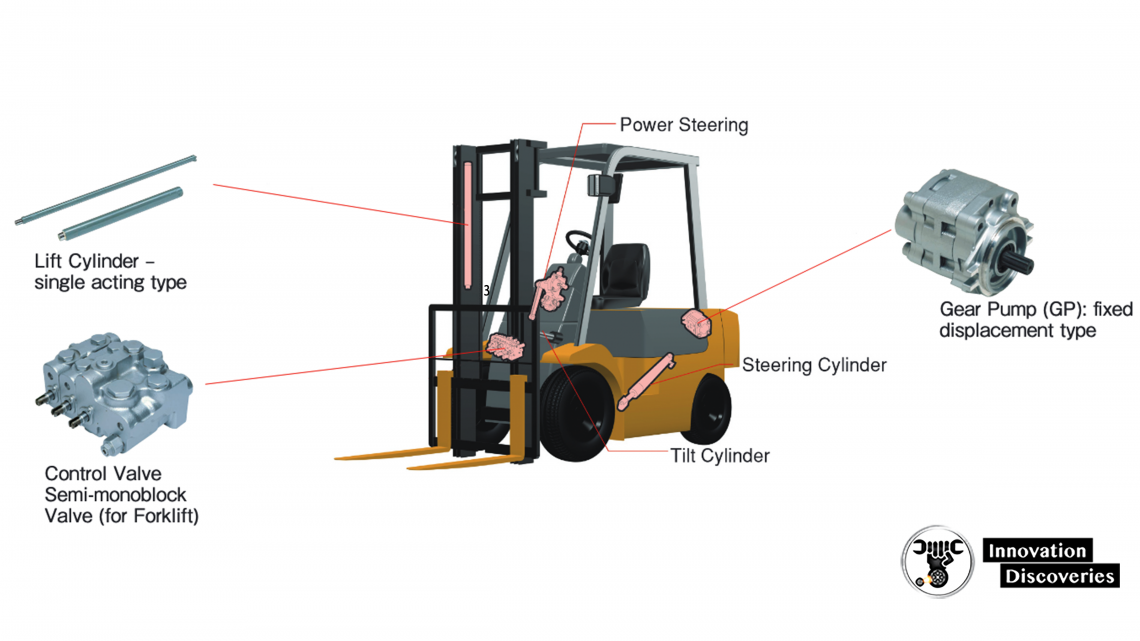
Hydraulic Equipment for 👇
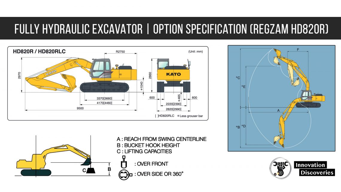
Excavators and Mini-excavators
Forklift Truck
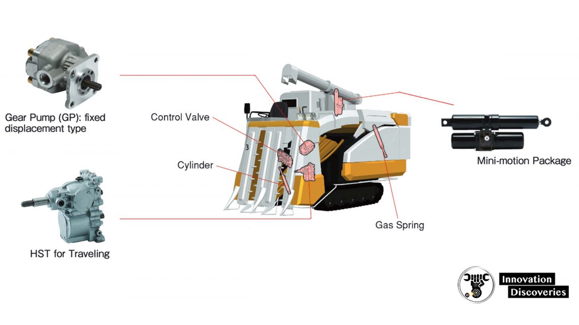
Combines
Precautions on the Use of Hydraulic Equipment
All Hydraulic Circuits
1. Pressure drop:
- Pressure drop is proportional to the square of the flow rate.
- Because the loss may increase depending on the specific equipment and the size and/or length of joints, the normal flow rate and the maximum flow rate being used also should be taken into account.
2. Circuit temperature control:
- The temperature of the hydraulic fluid in the entire circuit may rise because of the operation frequency and/or pressure drop.
- Consult the component manufacturer to make sure the reservoir and cooler capacity is sufficient.
Hydraulic Fluids
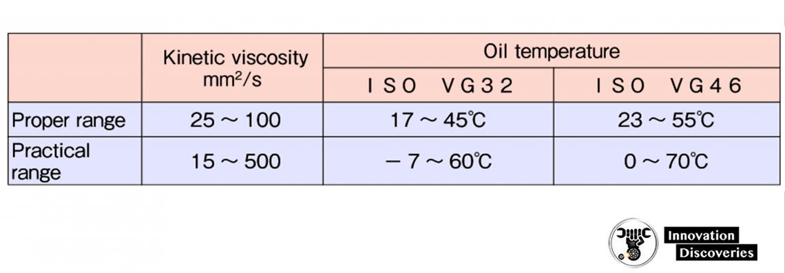
– Applicable hydraulic fluids
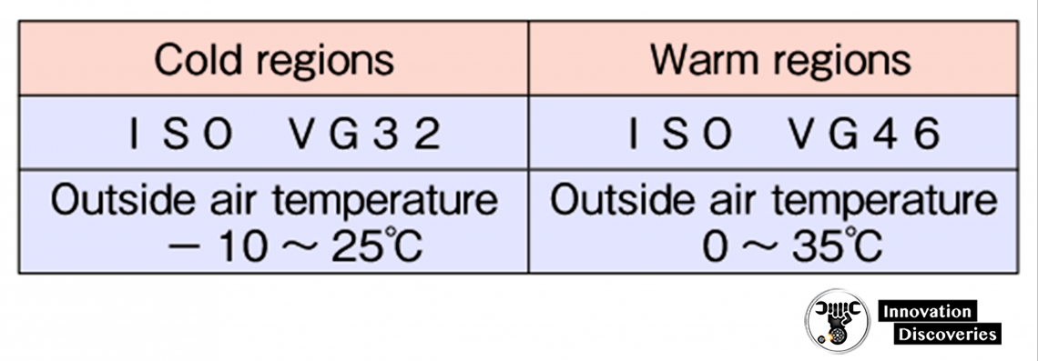
– Applicable hydraulic fluids
– Strainers and Filters
Apply a 150 mesh strainer to the suction line from a reservoir and a 10μm filter to the return line to the reservoir.
Determine the capacity based on the pump flow rate on the maximum input rotation and maintain the pressure drop below 0.03 MPa.
Hydraulic fluid contamination level control
It is recommended to maintain hydraulic fluid contamination within the NAS 9 class range.
– Circuit Oil Temperature
Permissible oil temperature range:
20°C (starting temperature) up to 100°C (total 100 hours), and between 20°C and 80°C for a continuous operation.
Please contact manufacture when you plan to use the equipment outside the permissible oil temperature range.
Precautions on Handling Pump/Motor
– Mounting
1. In general, the pump/motor can be mounted in any direction.
- But the drain piping should be connected to the reservoir at a point lower than the oil level after it is taken out from the upper surface of the pump/motor housing.
- This is to lubricate the reduction gears.
- Please note that the travel motor and the swing motor are to be mounted in the specified direction.
2. Make sure that the rotating direction is correct for both pump and motor.
3. Make sure there is some allowance between the pump shaft and driving shaft (with a motor or engine), and between the motor shaft and driven shaft (on the load side), in either case in the radial direction.
Avoid applying thrust load to the pump or motor shaft.
4. Maintain the center dislocation between the pump and driving shafts, and between the motor and driven shafts within 0.1 mm on FIR (full indicator reading).
– Selecting Shaft End Configuration
Select a shaft end configuration appropriate for the driving system based on the following pump and motor requirements.
1. Direct driving:
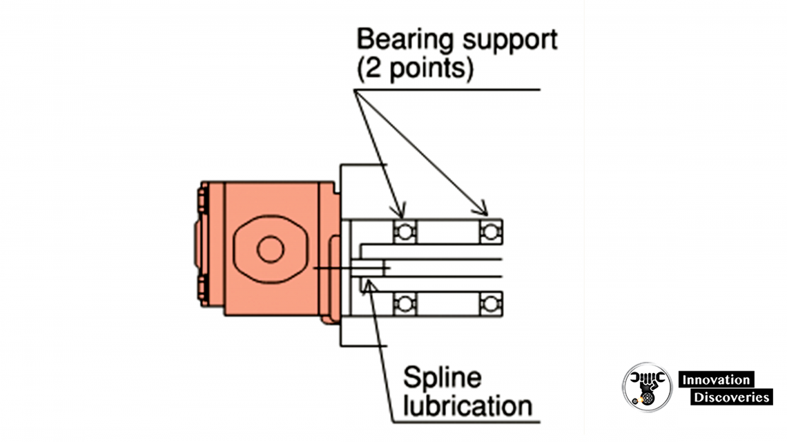
- When it is difficult to give some allowance in the radial direction, use a spline shaft.
- Make sure to apply lubricant and dust-protection to the spline.
- Selecting a counterpart spline with the surface hardness over HRC 50 and the surface roughness below 32a is recommended.
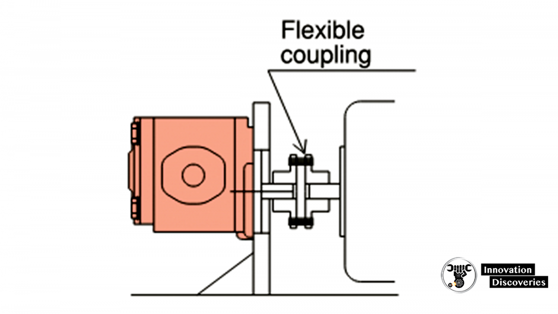
2. Coupling driving:
- When using a flexible coupling, select one with a straight shaft and assemble it in such a way that no thrust load is applied to the pump motor shaft. (See Fig. 2 below.)
3. Applicable shaft configurations vary depending on the product.
- Contact manufacturer for details
Pump/Motor Shaft Driving System
Spline shaft
Straight shaft
Pump Suction Pressure and Piping
- During a normal pump operation, maintain pressure on the pump suction port (less than 30 mm from the port surface) above -0.02 MPa.
- Pressure may come down as low as -0.05 MPa for a short while on a cold start, but air suction from the piping should be strictly avoided.
- For the suction side piping, use pipes with a diameter equal to or larger than the diameter of the pump suction port and try to keep the length as straight and short as possible.
Piston Pump Motor Drain Piping and Case Internal Pressure
- Drain piping is to be connected to the reservoir at the point lower than the reservoir oil level after being taken out from the point higher than the pump/motor housing.
- This is necessary for lubrication in reduction gears.
- Always keep the motor housing filled with oil.
- Otherwise, it will result in poor lubrication in the housing and cause the seizure of parts.
- Maintain the case internal pressure below 0.1 MPa.
- Higher drain pressure will shorten the life of internal parts. Smaller or longer piping will raise the internal pressure.
- Contact Manufacturer about the proper drain flow, which varies depending on the condition.
- Operating the product without drain piping will raise the pressure in housing and may cause internal damage or oil leakage.
- If you have done so, inspect and repair damage or replace the housing.
- (This will not apply to some pumps that do not need drain piping.)
- If you have done so, inspect and repair damage or replace the housing.
- Fill the housing with oil before starting an operation.
- Otherwise, it may cause an initial seizure.
Closed Circuit Pump and Motor Boost Pressure
- A closed circuit pump requires boost pressure of 0.3 to 0.5 MPa at the suction port.
- Lower boost pressure may cause cavitation, noise, poor braking, or damage to the pump.
Piston Motor Back Pressure
- If the output port of a motor in a series- or meter-out circuit is pressurized highly and constantly, the product life shortens.
- Excessive back pressure may damage the motor at an early stage of its life.
- Contact manufacturer for permissible maximum back pressure for each product.
Piston Motor Cavitation Prevention
- With a motor used in an open circuit, cavitation may occur at a low pressure area when the motor stops running.
- Install a cavitation preventive function in the circuit to avoid such damage
Precautionary Cylinder Handling
Initial Unpacking
- Do not remove the plug placed on the cylinder port until you start assembling the unit.
- Mount the cylinder on the prepared equipment right after unplugging it, and fill the cylinder with oil.
Rust Protection
- When leaving the rod extended after the cylinder is mounted on the equipment, apply grease to the exposed rod surface once a month.
Precautions on Valve Handling
On Assembly
- Do not remove the plug placed on each port until it is connected to the piping.
- When mounting a valve, use bolts of the right size and work on the provided flat mounting plate so as to protect the valve from the tightening torque.
- Use an operation link that does not apply a horizontal load to the spool. (Manual lever, etc.)
On Operation
- Set the valve lever at the neutral position when starting an operation.. Otherwise, it may cause the actuator to start running unexpectedly.
- Allowable maximum backpressure:
- The figure in the specifications includes a peak value at the tank port of the valve.
- A careful attention is also required when viscosity is high at a low temperature.
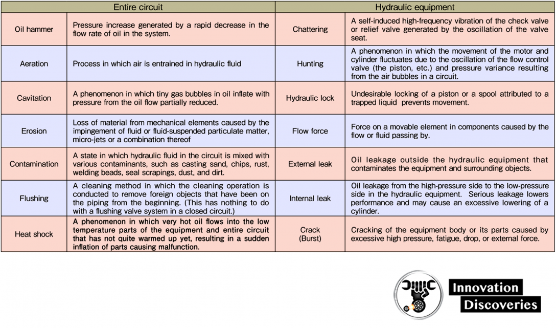
Definition of terms frequently used with hydraulic circuit trouble
Hydraulic Pump (General)
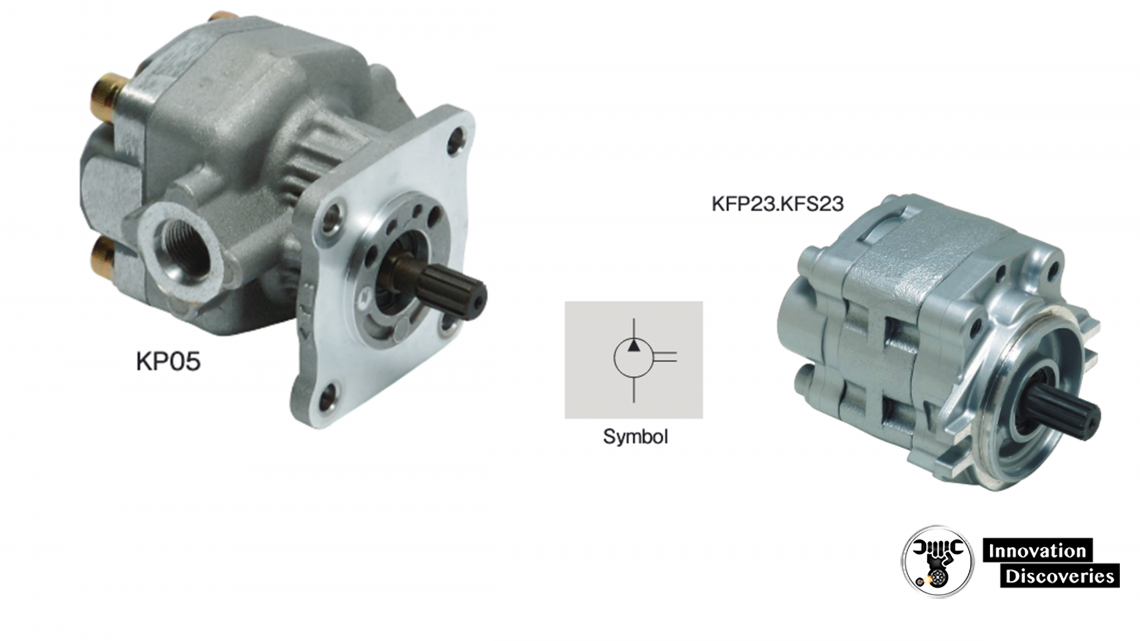
Basic Construction
Construction and Mechanism
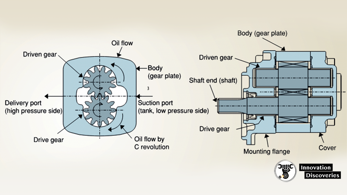
- The shaft connected to the gear is driven by an engine or an electric motor.
- While the gears are rotating, the oil filling the gear tooth grooves is moved from the suction port to the delivery port.
The shaft is designed to be rotated in one direction to realize high performance.
Direction of shaft rotation:
- C rotation (clockwise viewing from the shaft end)
- A rotation (anti-clockwise viewing from the shaft end)
Note: Rotating the pump in the direction opposite to the design will damage the inside of the pump and render it unusable
Basic characteristics
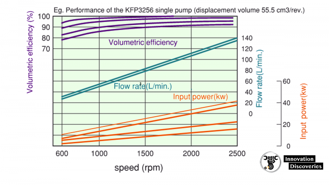
- Volumetric efficiency (actual flow / theoretical flow) Operation at a low speed and high pressure increases internal leakage causing low performance.
- Input power (theoretical shaft power / mechanical efficiency) Operation at a high speed and high pressure increases shaft power.
- The actual flow and actual input power are related to the speed
and pressure.
Displacement of each Model
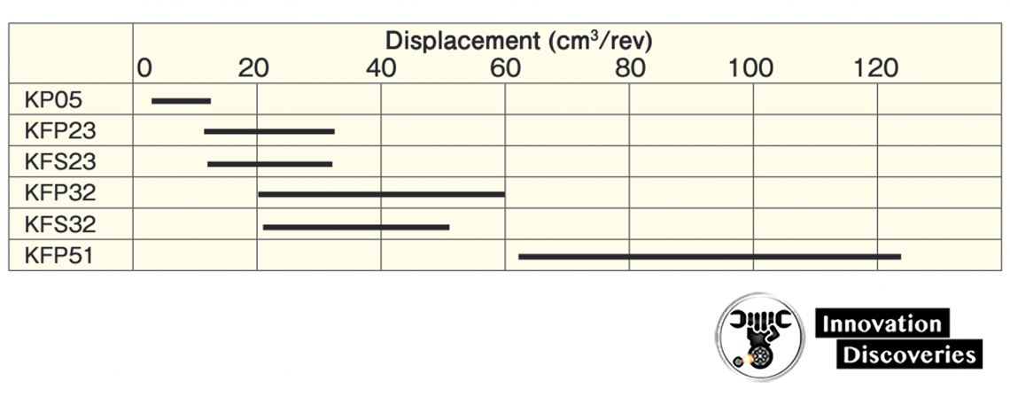
KP, KFP, and KFS Series (Single)
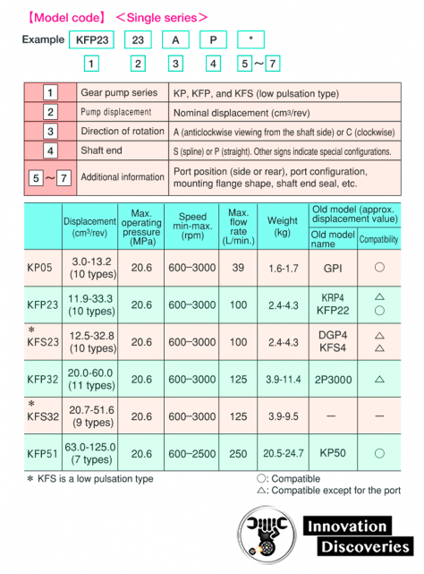
Low pulsation gear pump (KFS series)
- KFS23 series and KFS32 series are low pressure pulsation version of KFP23 series and KFP32 series.
- Noise in hydraulic systems is generally caused by the pressure pulsation created by the pump and dual flank engagement gear technology is utilized for these gear pump series to reduce the pressure pulsation.
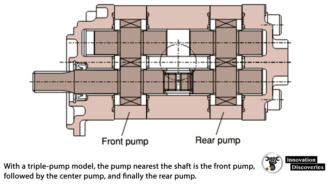
Caution to specify a tandem pump(Dual or Triple)
- Two or three pumps are driven with a single shaft.
- Specifications of each pump are the same as the single pump.
- Supply hydraulic fluid from the single reservoir, even if the front, center (in the triple model), and rear pumps have separate suction ports.
- Set the displacement volume as follows: Front pump ≧ Center pump ≧ Rear pump
- When only the front pump is operated, the maximum operating pressure may be applied.
- When multiple pumps are loaded simultaneously,
- however, the torque value (T value) in the following Q x P formula should not be exceeded.
Basic construction of tandem pump (dual model)
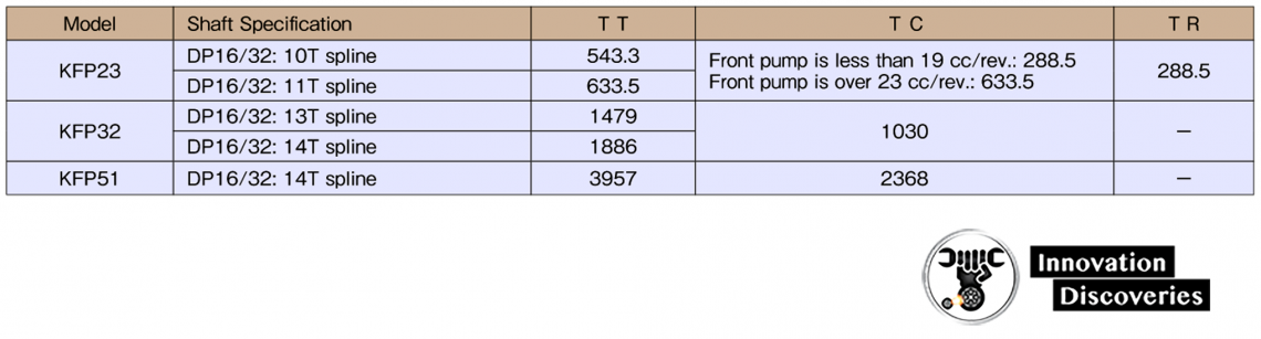
Q x P expression (T value)
- T values (TT, TR, and TC): Simple expression to obtain allowable shaft torsional torque
For dual model:
(QF × PF)+(QR × PR)≦ TT
QR × PR)≦ TR
For triple model:
(QF × PF)+(QC × PC)+(OR × PR)≦ TT
(QC × PC)+(QR × PR)≦ TC
(QR × PR)≦ TR
QF: Front pump displacement (cm3/rev)
PF: Front pump pressure (MPa)
QC: Center pump displacement (cm3/rev)
PC: Center pump pressure (MPa)
QR: Rear pump displacement (cm3/rev)
PR: Rear pump pressure (MPa)
TT, TC, and TR values
READ MORE: