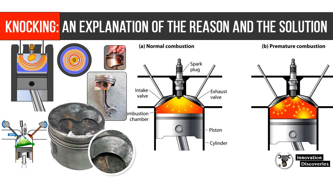
Knocking is a phenomenon of generating unwanted pressure wave which creates unpleasant sound and can damage engine wall during combustion in engines.
Knocking is largely associated with SI engines. It occurs due to the self-ignition of unburned charge into the combustion chamber.
When two flame fronts in SI engines collide, they produce an unwanted pressure wave which generates an unpleasant sound (knock-knock) and can damage the engine wall.
Engine Knocking :
Process:
Knocking is mainly associated with SI engines. It depends on the auto-ignition quality of fuel.
The higher auto-ignition temperature causes a lower down knocking tendency. To understand the whole concept of knocking let’s look at the combustion process.
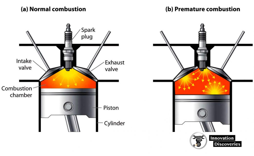
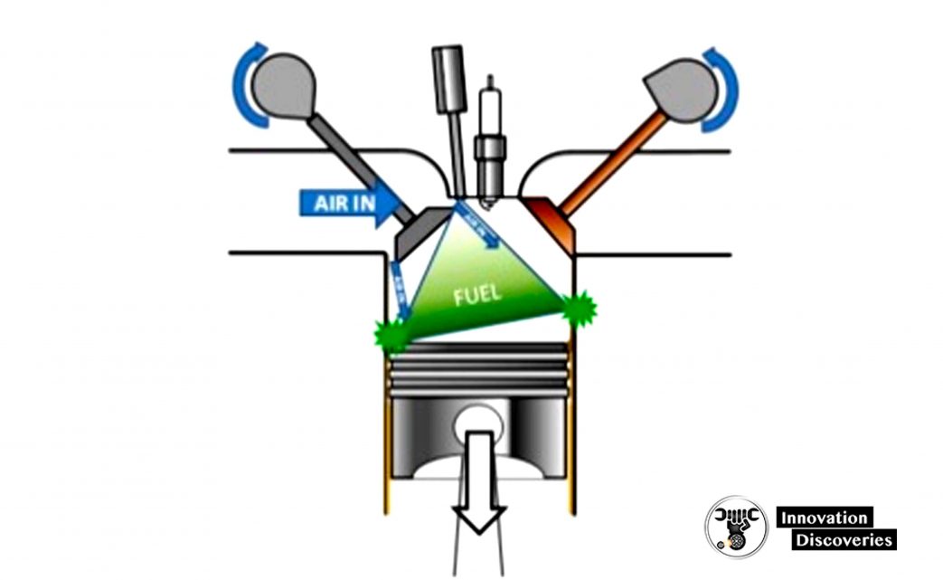
When the piston reaches TDC after compression, the spark plug produces a spark which ignites the compressed mixture and starts the combustion process.
It ignites only those part of mixture witch is in contact with the spark plug and generates the main flame front which further ignites the whole mixture.
This will generate high temperature and pressure forces inside the cylinder.
This burnt part of the mixture (combustion products) separates the fresh mixture from the spark plug to the other end of the cylinder.
As this flame front expands, it compressed the unburned part of the charge.
This compression increases the temperature and pressure of the unburned part of the mixture.
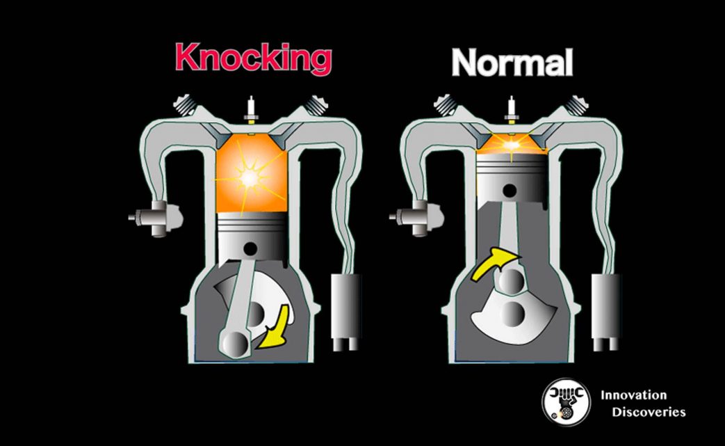
If the temperature of this part reaches its auto-ignition temperature, it will ignite from the other end and a new flame front starts moving towards the opposite direction of the main flame.
When both of these flame fronts collide, it will generate a high-pressure wave which produces an unpleasant sound and also damages the cylinder wall.
Factor affecting knocking:
Any factor which tends to decrease auto-ignition temperature of charge or tends to ignite the charge except spark plug will affect knocking.
The main affecting factor is given below.
Density factor:
The lower dense charge generates low energy and a lower rise in temperature thus avoid knocking.
If the density of charge decreases will decrease the knocking tendency. The factors which affect the density of charge are as follows:
Compression Ratio
An increase in compression ratio will increase the density of charge thus increase the knocking tendency.
Mass of the charge induced:
The mass of the charge depends on throttling or supercharging. A reduction in mass of induced charge reduces the knocking tendency.
Time Factor:
The lower the time available to auto-ignition will decrease the knocking tendency. The most affecting time factors are:
Engine Turbulence:
Turbulence reduces the ignition lag or time available for auto-ignition. So increase in turbulence will increase the main flame speed and reduce ignition lag, thus reduces knocking tendency.
Spark Plug Location:
To reduce the time available for auto ignition, a spark plug should locate to have minimum flame travel for proper combustion.
Generally spark plug located at the center to reduce the tendency of knocking.
Engine Size:
As the engine size increase will increase the flame travel thus increases the knocking tendency.
Combustion Chamber:
Combustion chamber design plays the main role in flame travel.
The more compact the combustion chamber has minimum flame travel distance thus reduce knocking tendency.
Also, the hot spot in the combustion chamber should be avoided which can ignite the charge.
Temperature Factor:
Any factor which increases the temperature of inside gases will increase the knocking tendency. These are
Inlet Temperature of Mixture:
More the inlet temperature of the mixture, increase the tendency of auto-ignition thus increase the knocking tendency.
Supercharging:
Supercharging increases both mass and temperature inside the cylinder thus increases the tendency of knocking.
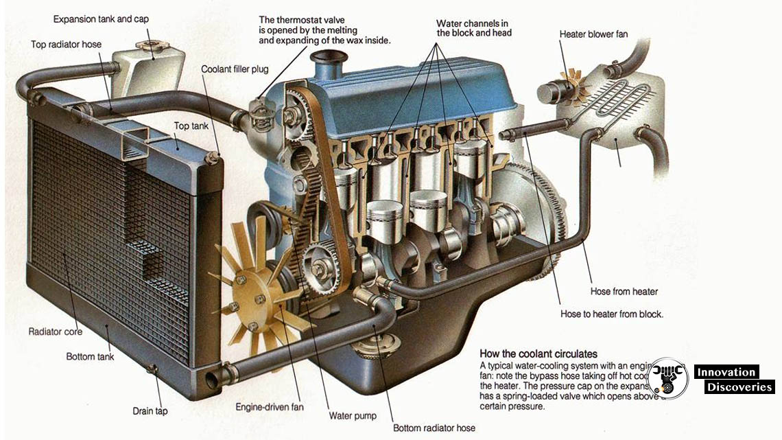
The temperature of Combustion Wall
It will play the main role in knocking. The higher the temperature of the wall, the more chance of auto ignition, thus more chance of knocking.
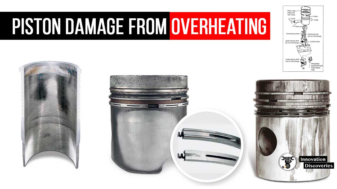
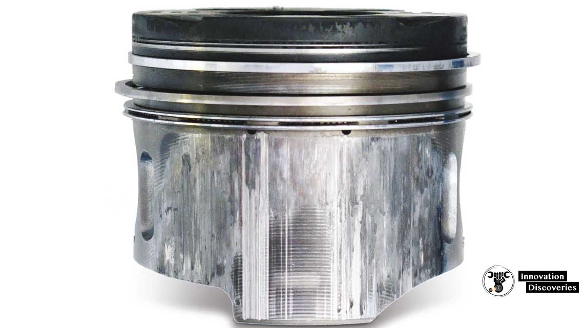
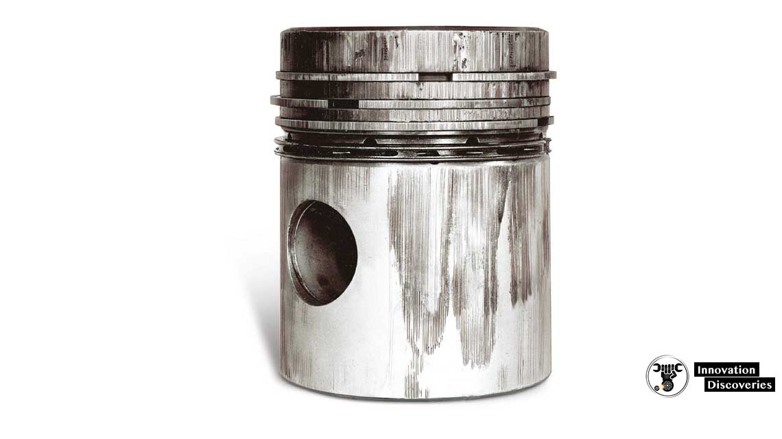
READ: PISTON DAMAGE FROM OVERHEATING

- WHAT IS PISTON CLEARANCE? AND WHY IT IS NECESSARY?
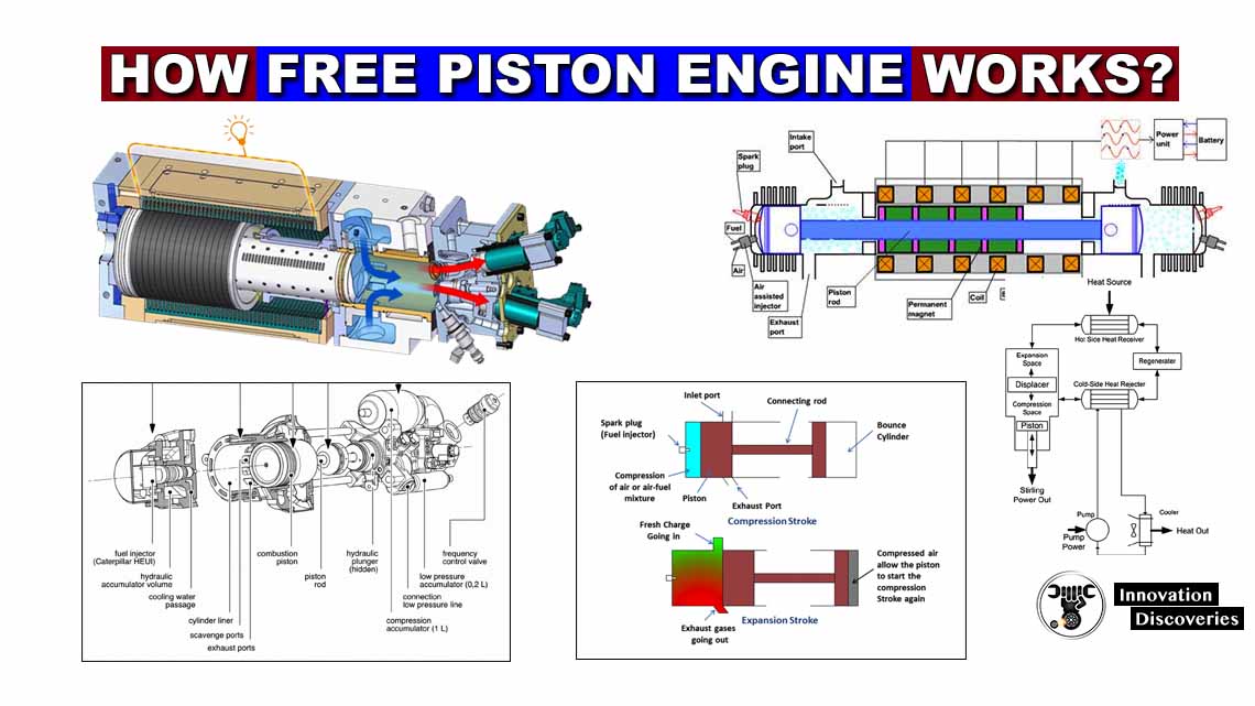
- HOW FREE PISTON ENGINE WORKS?
- HOW SUPER KNOCK CAN DESTROY MODERN ENGINES
DOWNLOAD PDF: FUEL SYSTEM FOR IC ENGINE | PDF
READ: IC ENGINE: COMPONENTS AND THEIR FUNCTIONS, TYPES, AND TERMINOLOGY
How to fix knocking:
We have known about the knocking phenomenon and factors affecting it. The most methods are used to avoid knock are as follows.
- Spark plug location should select to minimize the flame travel distance.
- By proper cooling of Engine wall.
- A combustion chamber is so designed which has less hot spots and higher turbulence.
- Uses higher auto-ignition temperature fuels or add additive in gasoline to increase its knocking temperature.
- Higher engine speed will reduce knocking.
- Reduce compression ratio.
- Reduce supercharging to avoid knocking.
For More Knowledge
Low-Speed Pre-Ignition
What is Low-Speed Pre-Ignition?
- Vehicle manufacturers are constantly trying to decrease fuel consumption while increasing speed-torque to the tires (or at least keep it the same). This is the definition of increasing fuel economy.
- In its simplest form, you want to increase engine pressure at the optimal engine speed. The engine is tuned to the ”power band”, where the fuel to (speed-torque) ratio is the lowest.
- For simplicity’s sake, the ”power band” exists when the engine speed is low and the engine pressure is very high. (1500 – 2500 RPM)
- Because of an emphasis on fuel economy, the “power band’s” torque is being elevated which is done by increasing pressure inside of the engine cylinder. We’re pushing the limit of what current combustion engines can accomplish.
- This increased pressure in the cylinder is causing a phenomenon called low-speed pre-ignition.
This is where the fuel is combusting before the spark plug fires. As you can imagine this is bad.
Think about when this happens on the up-stroke. It’s like hitting the top of the piston with a maul! This causes all kinds of damages.
Even broken rods!
•No one knows what causes this LSPI, but there are some theories and proven actions that minimize the amount of LSPI.
A CHART
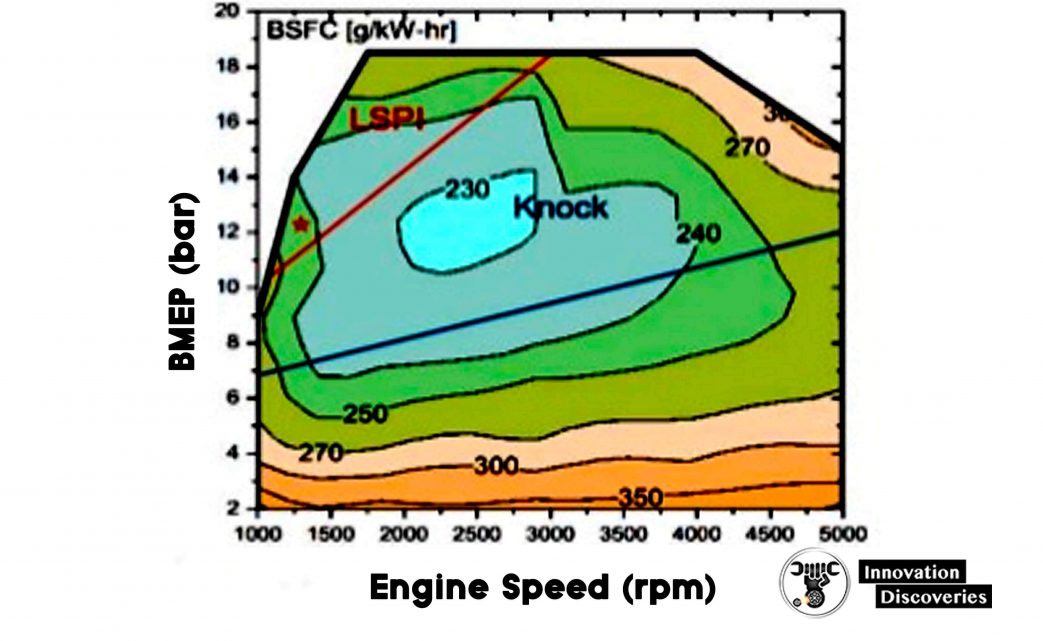
This chart will be explained fully over the next few slides, but as a general overview please note:
- The lower the number, the more fuel-efficient the vehicle is
- The area above the red line is the area where LSPI is likely to occur.
- The area below the blue line has higher, less fuel-efficient numbers, so are not optimal for the vehicle to be tuned to.
- This is a chart of a vehicle’s fuel to power ratio. It’s the whole vehicle system fuel economy combined into one chart.
What the heck does this chart mean?
If you search for LSPI, you’ll run across this chart.
It’s tough to digest mainly because it looks like a 2d graph, but it’s actually 4 dimensional, so you are looking at 4 variables, 2 of which are wrapped up in the color and map lines. Charted
- BMEP is basically pressured inside the cylinder (bar)
- Engine speed (rpm) Not inherently visible – BSFC
- Fuel consumption (g)
- Torque (Nm) Notice the number in the middle of the chart (230 in light blue), that’s the BSFC.
The lower the number, the better the fuel efficiency. This number is the amount of fuel versus the rpm- torque output.
For fuel economy reasons, we really want to operate in the LSPI region “power band”
Pressure vs Engine Speed Chart
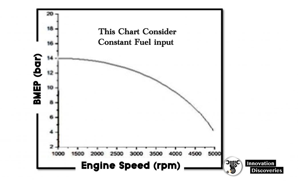
To start to understand LSPI we will simplify this chart by using constant fuel input and power output while assuming 100% energy conversion.
This chart represents a BMEP (pressure) vs. engine speed using a constant rate of fuel input.
It’s important to note, that the power output is constant too for this entire graph.
Power output is the speed/pressure (or torque) BMEP means ”Mean effective pressure” which is an average of cylinder pressure.
Introducing BSFC – Step 1
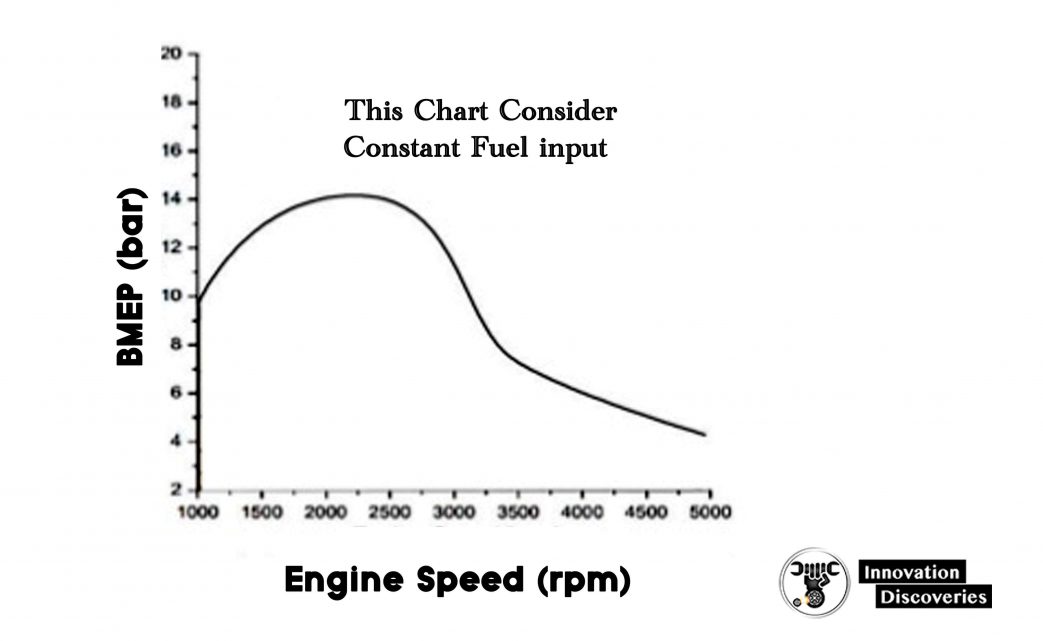
BSFC means brake-specific fuel consumption. Which is the correlation between fuel consumption and actual torque output.
As said before, there are 4 variables at play here. Fuel, pressure, RPM, and torque output. This is a realistic view of engine efficiency.
Still, we are considering constant fuel input and torque, but notice the speed is not constant.
The “power band” looks to be between 1000 and 3000 rpm. The POWER (which is rpm-torque) is at its highest level in that range.
So, the fuel/power ratio will be the highest in this range … for this fuel input level.
Introducing BSFC – Step 2
BSFC is the ratio of fuel to power.
𝑓𝑢𝑒𝑙 𝑝𝑜𝑤𝑒𝑟 = BSFC
As we alter the fuel input, the BSFC graph will change. Creating a 3-dimensional graph.
BSFC – Step 3
So the rings that you see on this graph are the fuel/power ratio.
It’s a topographical map (think upside mountains), the lower the number, the more fuel-efficient the engine is.
The light blue range (230) in the middle of this chart just happens to operate in a bad range which is near the LSPI area (above the red line).
LSPI is a type of knock that causes more engine damage that you can’t control by spark plug timing.
Where we operate our engines
So we want to operate near the LSPI range because there’s more area and it’s easier to keep an engine in that range under most conditions.
Using electronic control of the transmission, we keep the torque load in the area that keeps the engine near the LSPI region, which maximizes fuel efficiency.
The last few slides have explained the LSPI region which is really close to the optimal fuel-efficient region, and we sometimes drift into it.
Now we will talk about combating LSPI.
Low-Speed Pre-Ignition
- Happens at low speeds where the pressure is very high inside the cylinder
- It’s very bad for the engine, much worse than the typical knock!
- Combustion occurs spontaneously
- No one really knows why, but there are some interesting claims which point to:
- Calcium detergents are becoming superheated and auto-ignite the fuel
- Oil droplets are mixing with the fuel causing spontaneous combustion
- As vehicles get more power-dense and fuel-efficient LSPI will become a major issue because engines will get tuned closer and into the dangerous LSPI region.
Combating LSPI
- IT’S VERY IMPORTANT
- More and more vehicles are operating at or near this BSFC range that harbors LSPI
- OEMs such as General Motors and bodies such as API and ILSAC see the need to combat LSPI and will soon be requiring motor oils to pass LSPI tests to gain new service classifications
- It looks as the best way is to use a lubricant that is designed to combat LSPI.
- Detergents such as calcium, which are prone to cause LSPI will be used less and less
- Better friction modifiers such as molybdenum and phosphorous will be used to decrease engine temps and prevent deposit buildup
- Better base oils with higher lubricating boundaries will be used to help prevent LSPI occurrences.
- Higher quality finished lubricants will have to be used!