Learning Objectives:
- Study the parts of the lubricating system of the EFI engine.
- Working principle of the EFI lubricating system.
Introduction
If the heart of a car is its engine, then its brain must be the Engine Control Unit (ECU).
Also known as a Powertrain Control Module (PCM), the ECU optimizes engine performance by using sensors to decide how to control certain actuators in an engine.
A car’s ECU is primarily responsible for four tasks. Firstly, the ECU controls the fuel mixture.
Secondly, the ECU controls the idle speed. Thirdly, the ECU is responsible for ignition timing.
Lastly, in some applications, the ECU controls valve timing.
Before we talk about how the ECU accomplishes its tasks, let’s follow the path of a gasoline droplet that enters your gas tank.
Times have changed since the Down the Gasoline Trail video, so it’s time for an update.
Initially, after a gas droplet enters your gas tank (which is now made of plastic), it gets sucked up by an electric fuel pump.
The electric fuel pump usually comes in an in-tank module that consists of a pump, a filter, and a sending unit.
The sending unit uses a voltage divider to tell your gas gauge how much fuel you have left in your tank.
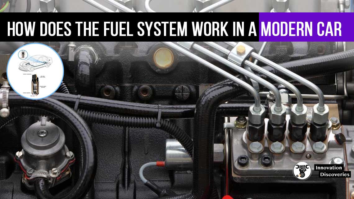
The pump sends the gasoline through a fuel filter, through hard fuel lines, and into a fuel rail.
A vacuum-powered fuel pressure regulator at the end of the fuel rail ensures that the fuel pressure in the rail remains constant relative to the intake pressure.
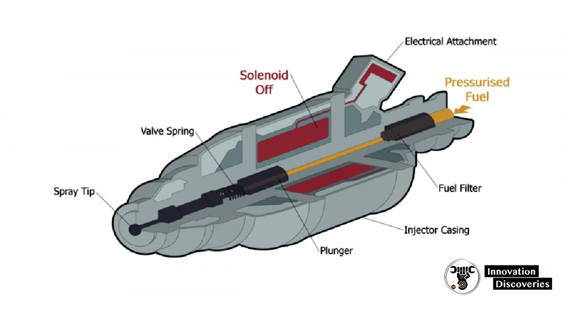
For a gasoline engine, fuel pressure is usually on the order of 35–50 psi. Fuel injectors connect to the rail, but their valves remain closed until the ECU decides to send fuel into the cylinders.
Usually, the injectors have two pins. One pin is connected to the battery through the ignition relay, and the other pin goes to the ECU.
The ECU sends a pulsing ground to the injector, which closes the circuit, providing the injector’s solenoid with the current.
The magnet on top of the plunger is attracted to the solenoid’s magnetic field, opening the valve.
Since there is high pressure in the rail, opening the valve sends fuel at a high velocity through the injector’s spray tip.
The duration that the valve is open- and consequently the amount of fuel sent into the cylinder- depends on the pulse width (i.e. how long the ECU sends the ground signal to the injector).
When the plunger rises, it opens a valve and the injector sends fuel through the spray tip and into either the intake manifold, just upstream of the intake valve, or directly into the cylinder.
The former system is called multiport fuel injection and the latter is direct injection.
Engine Throttle Working
We’ve already looked at how electronic throttle control works.
We showed you that, when a driver pushes his or her gas pedal, an accelerator pedal position sensor (APP) sends a signal to the ECU, which then commands the throttle to open.
The ECU takes information from the throttle position sensor and APP until the throttle has reached the desired position set by the driver. But what happens next?
Either a mass air flow sensor (MAF) or a Manifold Absolute Pressor Sensor (MAP) determines how much air is entering the throttle body and sends the information to the ECU.
The ECU uses the information to decide how much fuel to inject into the cylinders to keep the mixture stoichiometric.
The computer continually uses the TPS to check the throttle’s position and the MAF or MAP sensor to check how much air is flowing through the intake to adjust the pulse sent to the injectors, ensuring that the appropriate amount of fuel gets injected into the incoming air.
In addition, the ECU uses the o2 sensors to figure out how much oxygen is in the exhaust.
The oxygen content in the exhaust provides an indication of how well the fuel is burning.
Between the MAF sensors and the 02 sensors, the computer fine-tunes the pulse that it sends to the injectors.
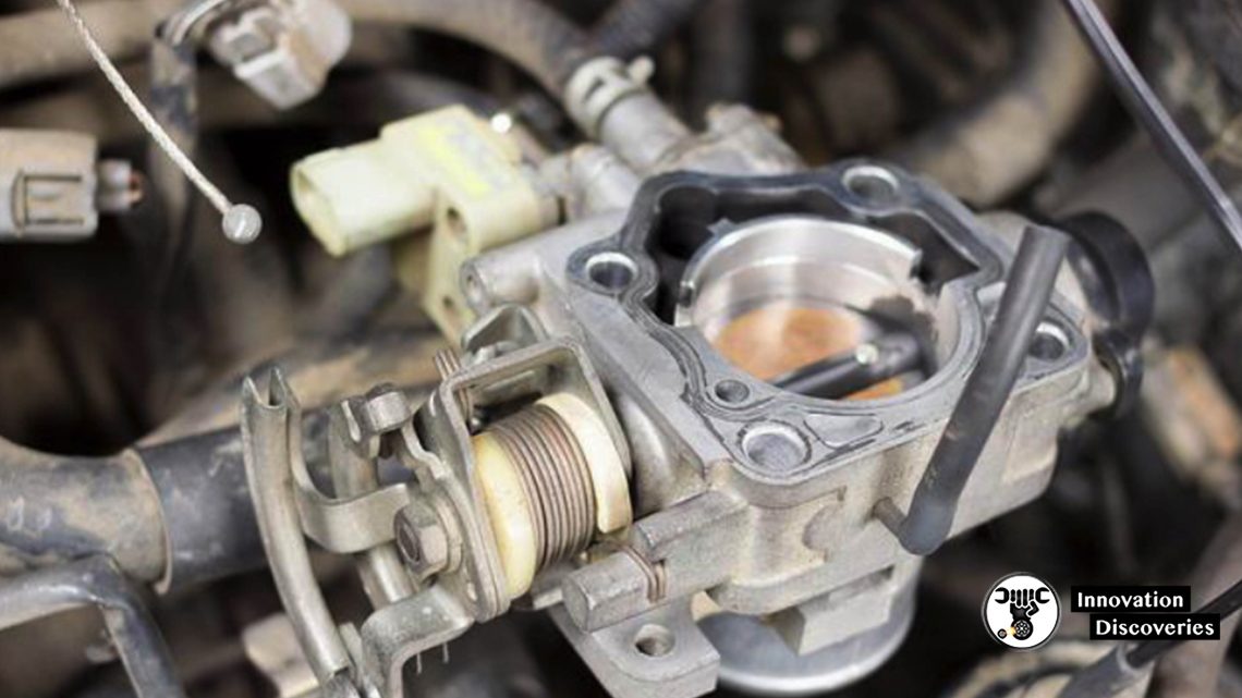
Controlling Idle
Let’s talk about idling. Most early fuel-injected vehicles utilized a solenoid-based idle air control valve (IAC) to vary airflow into the engine during idle (see the white plug in the above image).
Controlled by the ECU, the IAC bypasses the throttle valve and allows the computer to ensure a smooth idle when the driver does not activate the accelerator pedal.
The IAC is similar to a fuel injector in that they both alter fluid flow via a solenoid-actuated pin.
Most new cars don’t have IAC valves. With older cable-controlled throttles, the air entering the engine during idle had to go around the throttle plate.
Today, that’s not the case, as Electronic Throttle Control systems allow the ECU to open and close the butterfly valve via a stepper motor.
The ECU monitors the rotational speed of the engine via a crankshaft position sensor, which is commonly a Hall Effect sensor or optical sensor that reads the rotational speed of the crank pulley, engine flywheel, or the crankshaft itself.
The ECU sends fuel to the engine based on how fast the crankshaft rotates, which is directly related to the load on the engine.
Let’s say you turn on your air conditioning or shift your vehicle into drive. The speed of your crankshaft will decrease below the threshold speed set by the ECU due to the added load.
The crankshaft position sensor will communicate this decreased engine speed to the ECU, which will then open the throttle more and send longer pulses to the injectors, adding more fuel to compensate for the increased engine load.
This is the beauty of feedback control.
Why does your engine rev higher at startup?
When you initially turn on the vehicle, the ECU checks the engine temperature via a coolant temperature sensor.
If it notices that the engine is cold, it sets a higher idle threshold to warm the engine up.
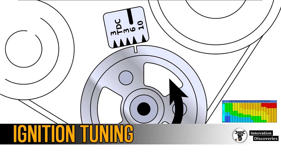
Controlling Ignition Timing
Now that we’ve mentioned the ECU’s tasks of maintaining engine idle speed, as well as maintaining a proper air/fuel mixture, let’s talk about ignition timing.
To achieve optimum operation, the spark plug must be provided with current at very precise moments, usually about 10 to 40 crankshaft degrees prior to the top dead center depending on engine speed.
The exact moment that the spark plug fires relative to the piston’s position are optimized to facilitate the development of peak pressure.
This allows the engine to recover a maximum amount of work from the expanding gas.
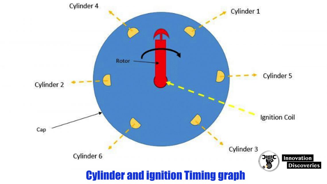
Older engines (up until the mid-2000s) used distributors to control spark. As shown above, this system consists of a rotor and a distributor cap.
The rotor is electrically connected to the ignition coil, which is a transformer that steps 12v up to over 10,000 volts needed for spark.
The rotor is mechanically connected to the camshaft via a gear. As the camshaft spins, so does the rotor.
As the rotor spins, it comes very close to copper posts (one for each cylinder).
The current from the ignition coil jumps the small air gap between the rotor and the posts, sending a high voltage through spark plug wires, to each cylinder’s spark plug at a specific time.
Note that these systems needed a way to alter timing. At high engine speeds, an advancing spark is necessary.
Early engines with distributors used engine vacuum or rotating weights to adjust timing. Later, transistor-based timing systems became more common.
Modern vehicles don’t use a centrally located ignition coil. Instead, these distributors’ ignition systems (DIS) have a coil located on each spark plug.
Based on input from the crankshaft position sensor, knock sensor, coolant temperature sensor, mass airflow sensor, throttle position sensor, and others, the ECU determines when to trigger a driver transistor, which then energizes the appropriate coil.
The ECU can monitor the piston’s position via the crankshaft position sensor.
The ECU continually receives information from the crankshaft position sensor and uses it to optimize spark timing.
If the ECU receives information from the knock sensor (which is nothing more than a small microphone) that the engine has developed a knock (which is often caused by premature spark ignition), the ECU can retard ignition timing to alleviate the knock.
Controlling Valve Timing
The fourth major function of the ECU is to adjust valve timing.
This applies to vehicles that utilize variable valve timing, which allows engines to achieve optimal efficiency at a multitude of engine speeds.
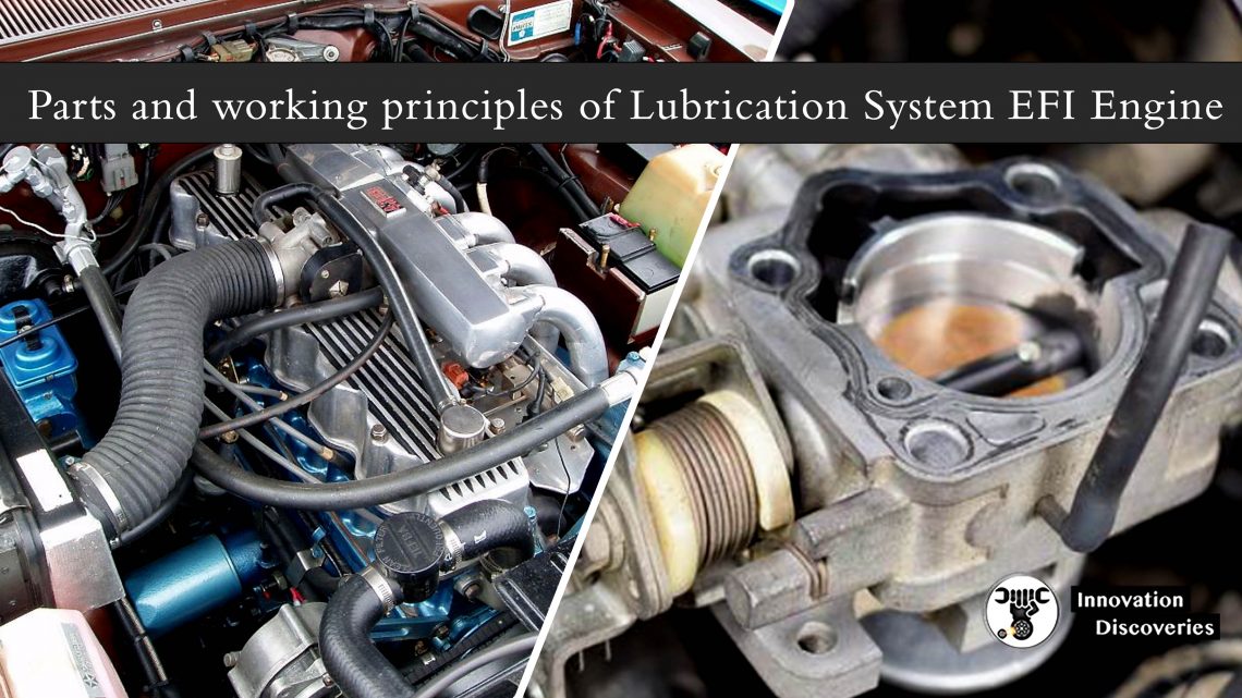
Lubricating System
When it comes to day-to-day car maintenance, your first concern is probably the amount of gas in your car. How does the gas that you put in power the cylinders?
The engine’s fuel system pumps gas from the gas tank and mixes it with air so that the proper air/fuel mixture can flow into the cylinders.
Fuel is delivered in three common ways: carburetion, port fuel injection and direct fuel injection.
- In carburetion, a device called a carburetor mixes gas into air as the air flows into the engine.
- In a fuel-injected engine, the right amount of fuel is injected individually into each cylinder either right above the intake valve (port fuel injection) or directly into the cylinder (direct fuel injection)
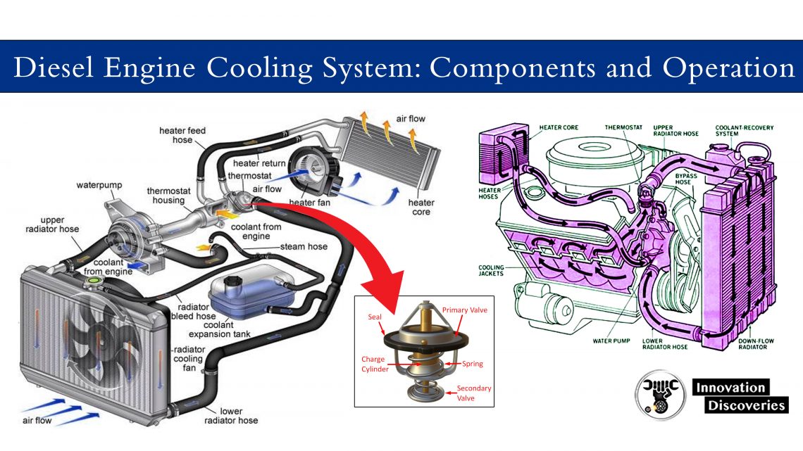
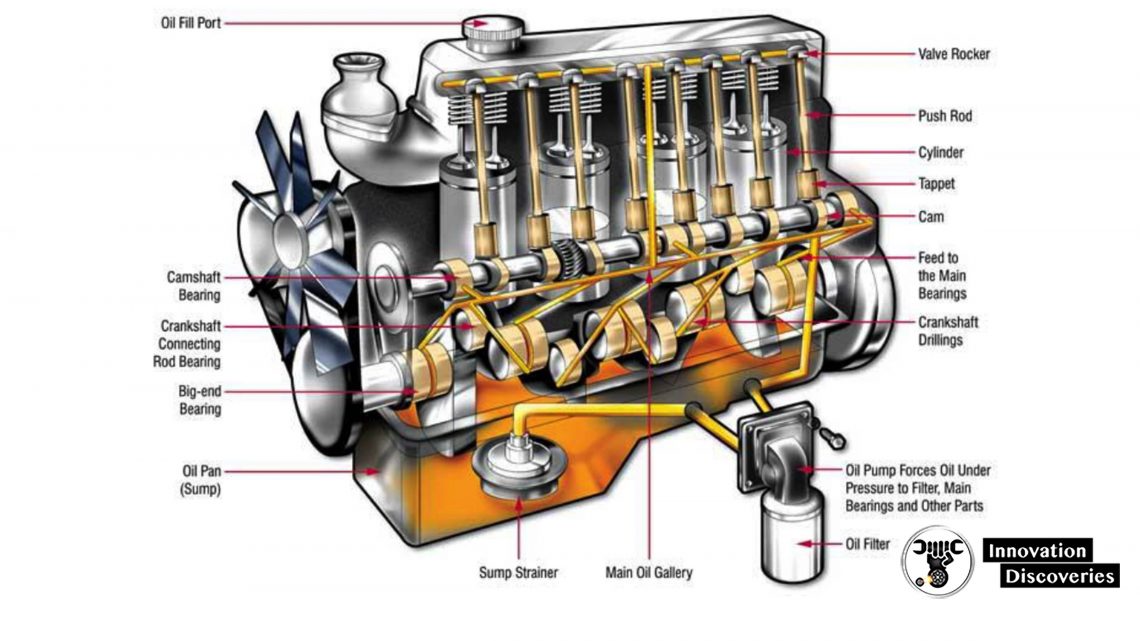
Oil also plays an important part. The lubrication system makes sure that every moving part in the engine gets oil so that it can move easily.
The two main parts needing oil are the pistons (so they can slide easily in their cylinders) and any bearings that allow things like the crankshaft and camshafts to rotate freely.
In most cars, oil is sucked out of the oil pan by the oil pump, run through the oil filter to remove any grit, and then squirted under high pressure onto bearings and the cylinder walls.
The oil then trickles down into the sump, where it is collected again and the cycle repeats.
Now that you know about some of the stuff that you put in your car, let’s look at some of the stuff that comes out of it.
The exhaust system includes the exhaust pipe and the muffler. Without a muffler, what you would hear is the sound of thousands of small explosions coming out your tailpipe.
A muffler dampens the sound. The exhaust system also includes a catalytic converter. See How Catalytic Converters Work for details.
The emission control system in modern cars consists of a catalytic converter, a collection of sensors and actuators, and a computer to monitor and adjust everything.
For example, the catalytic converter uses a catalyst and oxygen to burn off any unused fuel and certain other chemicals in the exhaust.
An oxygen sensor in the exhaust stream makes sure there is enough oxygen available for the catalyst to work and adjusts things if necessary.
Besides gas, what else powers your car? The electrical system consists of a battery and an alternator.
The alternator is connected to the engine by a belt and generates electricity to recharge the battery.
The battery makes 12-volt power available to everything in the car needing electricity (the ignition system, radio, headlights, windshield wipers, power windows and seats, computers, etc.) through the vehicle’s wiring.
Discover More: