Wheels are an integral part of your ride’s look and performance. Nothing enhances the look of a vehicle like a new set of aftermarket wheels and tires. But, wheels come in a dizzying array of sizes, styles, and materials. There are so many types of wheels and the terminology for wheel parts can be confusing.
Arm yourself with information before you shop for wheels. This guide will help you dive deep into the names of wheel parts, dissect wheel anatomy, learn how wheels are made, why wheel size matters, how to measure wheel offset, the ins and outs of up-sizing wheels and much more. There’s even a glossary of terms for quick reference.
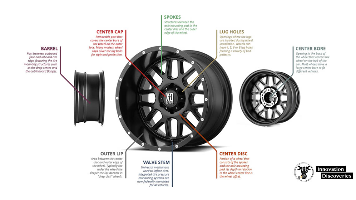
PARTS OF A WHEEL
A wheel might look like a single object, but it is made up of several parts. To understand a wheel, you must understand the parts of a wheel. Let’s get acquainted with the most important wheel parts by starting at the center of the wheel.
1. Center bore
The center bore is the opening that
allows the wheel to fit on the axle. This is the part of the wheel that
actually attaches the wheel to the vehicle and bears the weight of the
vehicle. When you buy aftermarket wheels, you must ensure that the
center bore is at least the size of the OEM wheel. This generally isn’t a
problem as most manufacturers make wheels with a large center bore in
order to fit as many vehicles as possible. When the center bore is
larger, hubcentric rings are used to fill the gap. Center caps will
cover the center bore with style.
2. Center disc
Going out
from the center bore is the center disc. This is the portion of the
wheel into which the bolt holes are machined to create the bolt circle.
This area is the point of contact to the axle seat, the lug bolts and
the lateral surface of the rotor. Everything on the wheel connects in
some manner to the disc.
3. Lug holes
The lug holes create
the bolt circle with 4 or more openings. The diameter of the bolt circle
is called the bolt circle diameter and abbreviated as BCD. The amount
of holes and the diameter of the bolt circle is what defines the bolt
pattern. Now that we’ve got the center covered, let’s move outward in
our wheel anatomy.
4. Spokes
The spokes connect the center
disc to the outer ring of the wheel. The spokes give the wheel
structural integrity and are one of the major elements of style in wheel
design.
5. Outer lip
The outer lip is the portion of the
wheel in front of the spokes. For the most part, the dish only comes
into play when it is a large area. When the spokes are significantly
distanced from the outer edge, the wheel is considered a deep dish
wheel. This is done purely for aesthetic reasons. As the dish gets
deeper, the face is more vulnerable to damage from impact.
6. Barrel
Now, on the very outer portion of the wheel is the barrel. The barrel
is what creates the structures necessary for mounting the tire. The
barrel has many parts. The smallest inside diameter of the barrel is the
drop center. If the drop center is close to the front face of the
wheel, it is a front mount wheel. If the drop enter is close to the back
face of the wheel it is a reverse mount wheel. The barrel edges are
flared to create the flanges. The flanges keep the tire from slipping
off. The outer facing flanges are part of the cosmetic face of the
wheel.
7. Beads
Just inside the flanges are flat areas
called the beads. This is where the edges of the tire sit onto the
wheel. Mounting humps circle the barrel on both the car side and the
cosmetic side of the wheel. These ridges separate the beads to keep the
tire from slipping away from the edge of the wheel.
HOW WHEELS ARE MADE?
Different types of wheels are formed by different types of manufacturing methods. The wheel structure and the wheel material determine the manufacturing process used. Here are the most common methods used to make aluminum and alloy wheels.
1. Casting
This is the simplest method of manufacturing a wheel. Molten metal is
poured into a mold to create the wheel. With gravity casting, the
pressure of gravity pushes the metal into the mold. Pressure casting
uses additional pressure to compress the metal into the mold. Low
pressure casting uses air to force the molten metal into the mold and
compress the metal. Counterpressure casting uses the suction force of a
vacuum to pull the molten metal into the mold. Casting is used to create
a one-piece wheel structure.
2. Flow Forming
This combines a
casting process with a stretching process. First the metal is poured
into a mold and then heat and high pressure rollers are used to shape,
stretch and form the wheel. This process creates a thin but dense metal.
That means light, but strong.
3. Forging
This process is
popular with aluminum and some aluminum alloys. An aluminum billet (a
block of metal) is the starting point. The billet is then crushed into
shape using an unbelievable amount of pressure. This creates a wheel
structure that is dense, strong, and light.
4. Rotary Forging
This process was pioneered by TSW Wheels and is being used by Motegi
Racing Wheelsas well. It is similar to standard aluminum forging but
with a twist. While the billet is being forged, the forge is spinning at
high speeds. This forces the molecules to form strong chains. This
structure results in a wheel that is stronger than a conventionally
forged aluminum wheel.
WHEEL SIZES
Wheels come in a wide range of sizes. The low-end is anchored by 15 inch wheels; massive 26 inch wheels dominate the upper end and wheels of all sizes are available in-between. So, if your car or truck comes stock with 16 inch wheels why would you want another size? Two reasons: aesthetic appeal and performance.
Larger wheels just look better. They fill out the wheel well and that provides visual impact. It’s what we call pure wheel eye candy. Larger wheels carry tires with smaller sidewalls so you get better grip and performance. For off road vehicles, this translates to less roll and sway and more stability. The only downsides to upsizing are that larger wheels and tires weigh more so gas mileage suffers and acceleration from 0 to 60 is degraded. Car and Driver studies also determined that at the upper limits, the suspension is taxed and the ride can suffer.
Don’t forget, your vehicle was originally engineered to roll on stock size wheels. That means the speedometer, odometer, traction control, torque and gearing settings were based on the distance that the stock wheel and tire assembly would cover in one revolution. When you change the size of the wheel you must maintain the overall diameter of the wheel and tire assembly. So, as your wheels get larger, the standing size of the tire gets smaller.
A good rule of thumb is that for every increased inch of wheel diameter you must decrease an inch of standing height. This maintains the overall diameter. That means the wheel and tire will still cover the same amount of distance in one rotation but it will look so much better doing so.
A wheel size is expressed as follows:
DxW
Where D = diameter and W = width.
For example: 18×9 means the diameter of the wheel is 18 inches and the width is 9 inches.
• 15×10 wheels
• 17×9 wheels
• 20×10 wheels
• 20×12 wheels
• 20×14 wheels
• 22×12 wheels
• 22×14 wheels
BOLT PATTERNS
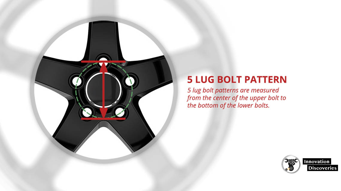
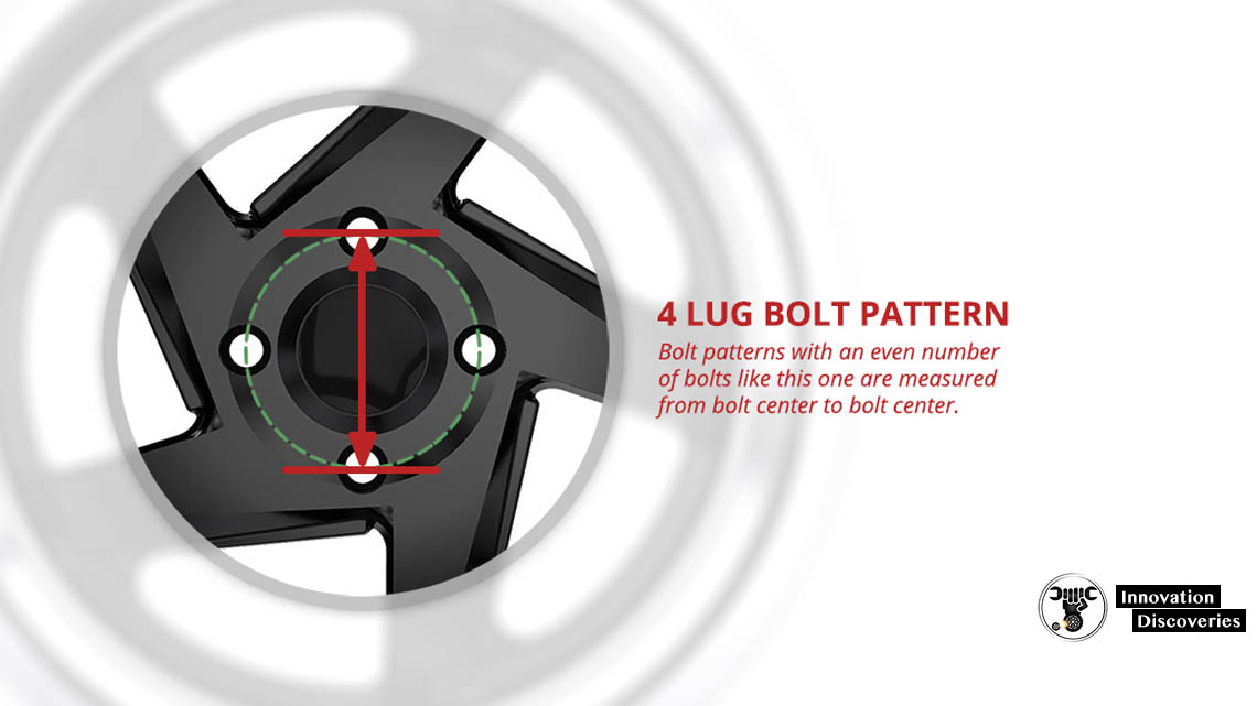
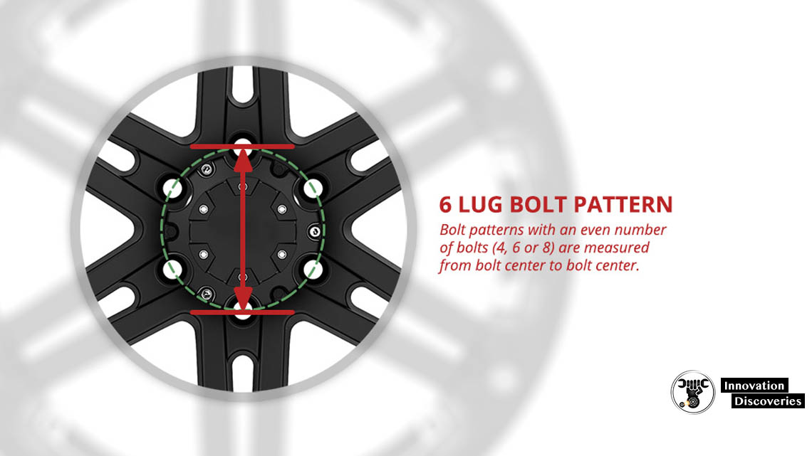
The bolt pattern is made up of the number of bolts and the diameter of the imaginary circle they create (BCD). The BCD can be expressed in inches or millimeters. Bolt patterns with an even number of bolts are measured from bolt center to bolt center. 5 lug bolt patterns are measured from the center of the upper bolt to the bottom of the lower bolts.
A bolt pattern is expressed as follows:
NxBCD
Where N = number of bolts and BCD = bolt center diameter.
For example, if you have a 5 lug wheel and your bolt center measures 114.3 millimeters then your bolt pattern is 5×114.3.
Here are examples of common bolt patterns. Each link lets you browse existing wheels with that bolt pattern:
• 4×100 wheels
• 4×114.3 wheels
• 5×100 wheels
• 5×112 wheels
• 5×114.3 wheels
• 5×120 wheels
WHEEL OFFSET
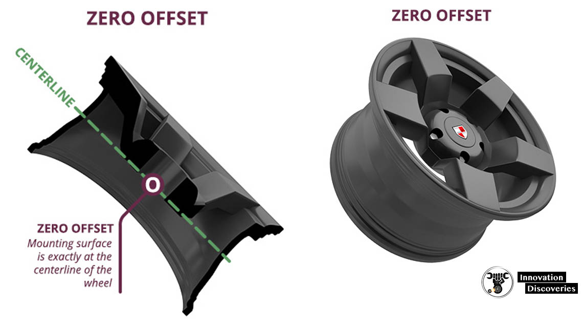
The offset may be one of the most difficult parts of the wheel to understand. Offset measures the distance from the center-line of the wheel to the mounting surface. It is measured in millimeters. It can be a zero, positive, or negative offset.
• With a 0 (zero) offset, the mounting surface is exactly in the center of the wheel.
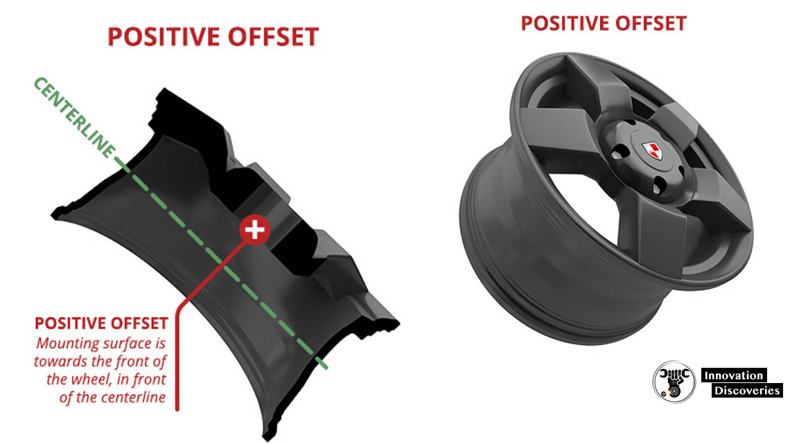
• With a positive offset, the mounting surface is to the front of the wheel. It is expressed as the number of millimeters from the center-line.
• With a negative offset, the mounting surface is to the back side of the wheel. It is expressed as the number of millimeters from the center-line.
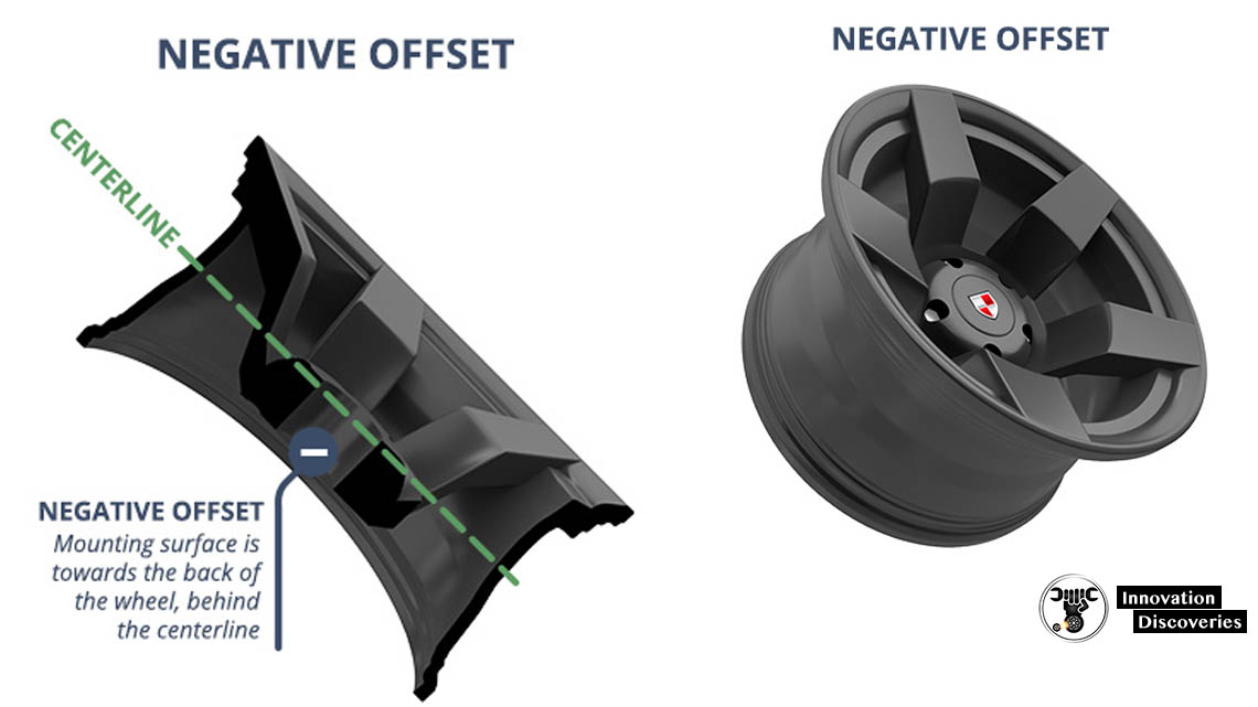
For example, if a wheel is 9 inches wide, the center-line is at 4.5 inches. A positive offset is the number of millimeters beyond 4.5 inches and a negative offset would be the number of millimeters in the opposite direction.
A positive offset makes the wheels look like they are coming further out from the wheel well and a negative offset makes the wheels look like they are deeper in the wheel well.
One Piece Wheels Versus Two Piece Wheels
There are two types of wheels: one-piece wheels and two-piece or multi-piece wheels.
1. One Piece Wheels
The majority of wheels is one-piece wheels. That means that the entire wheel is cast or forged as one piece. One-piece wheels are stiffer than two-piece wheels.
2. Two Piece Wheels
Two-piece wheels are formed as the name implies, in two pieces. The center portion is one piece, the outer portion is the other piece and the two pieces are bolted together. The result is a very strong wheel.
Why should you care about the difference? Because two-piece wheels can combine finishes and alloys that aren’t possible with one-piece wheels. The manufacturer can also combine different widths and thicknesses of the metal in one wheel. They can also combine widths and offsets for more options in fitment.
If a two-piece wheel is damaged, you may not need to replace the entire wheel. You may be able to replace just the damaged portion.
DEFINITIONS/ GLOSSARY
Barrel
The outermost part of the wheel. This is the area where the tire is mounted.
Bead
The inner portion of the flange where the tire edge connects with the wheel.
Bolt Circle
The circle created by the bolt holes. The diameter of the circle is the Bolt Center Diameter (BCD).
Bolt Pattern
The number of bolts plus the bolt center diameter. It is expressed as N x BCD or a 5 bolts in a 4 �” diameter would be a 5×4.5″ bolt pattern.
Casting
A wheel manufacturing method where molten metal or metal alloy is poured into a mold to form the wheel.
Center Bore
Opening in the center of the wheel that allows the wheel to fit on the vehicle.
Center Cap
The wheel part that covers the center bore of the wheel on the outer face of the wheel.
Deep Dish Wheel
A wheel where the spokes considerably below the lip.
Dish
The portion of the wheel behind the spokes.
Drop Center
Ring-like area around the barrel that is closest to the centerline. It is the smallest inside diameter of the barrel of the wheel.
Flanges
The flared outer portion of the barrel that keeps the tire on the wheel. There are outer and inner flanges. The outward facing flanges are part of the cosmetic face of the wheel.
Front Mount Wheel
A wheel where the drop center is close to the front face of the wheel.
Hubcentric
When the center hole of the wheel is the center bore. Hub-centric wheels are mounted and balanced using the standard cone system used by computer balancers to balance off car.
Hubcentric rings
These are hard plastic spacers placed between the wheel hub and the center bore. Hubcentric rings allow you to purchase wheels with a larger center bore than OEM.
Lug-Centric
With a lug-centric design, the wheels are centered by the torque of the lug nuts and not the center bore of the wheel. These wheels are not balanced with the standard cone system. They must be balanced with their lug bolt pattern.
Mounting Humps
Ridges that separate the beads to keep the tire from slipping away from the edge of the wheel.
Offset
The distance in millimeters from the centerline of the wheel to the mounting surface. It can be zero, positive or negative.
Outboard
The structural part face of the wheel. It is the part that looks outward and gives the wheel it’s cosmetic appearance.
Reverse Mount Wheel
A wheel where the drop enter is close to the back face of the wheel.
Rim
The true rim definition is just the outermost portion of a wheel. However, rim is often used interchangeably with wheel.
Spokes
That portion of the wheel that connects the outer ring of the wheel to the wheel plate.
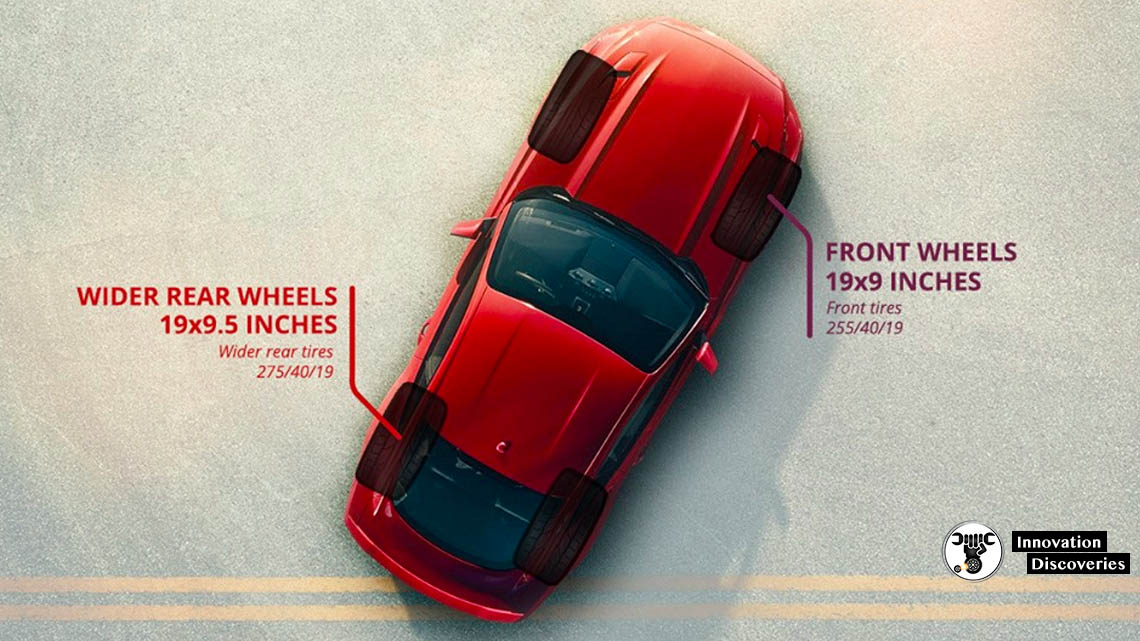
Staggered
A custom fitment where the rear wheels are wider than the front wheels.
Upsize
To increase the diameter of the stock wheel. When upsizing wheels, you must compensate by decreasing the standing height of the tire to maintain total diameter.
Wheel
The entire part on which a tire is mounted. The wheel includes the hub, spokes, and rim.
Wheel Plate
The point of contact for the axle seat, the lug bolts and the lateral surface of the rotor.
4 Comments