The light sources such as tube light or bulbs blink according to their particular watt rating.
If you need lighter, then you have to use high watt bulb and if you need low light, then you have to replace it with a low watt rating bulb.
But, if there is not needed to change the brightness of the light from the same light source. Here is the simple light dimmer circuit project, Which is used to control the brightness of the light according to our requirement.
This light dimmer circuit is used to control the voltage which gets to the light.
This circuit has been possible for many decades by using variable transformers and resistors.
These methods have been used in public places like theaters and stage lighting,
Homes, conference halls, restaurants, etc. But, light controlling methods are inexpensive, Big and efficiency is less, and they are very hard to control for the remote areas.
In the year between 1960 and 1970, power electronics have increased rapidly, TRIACs and thyristors came to the market.
It is very easy to design small and low-cost Light dimmer circuits with high efficiency.
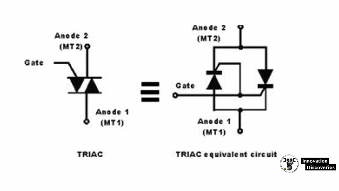
What is TRIAC?
The TRIAC is a three-terminal component that is used to control the current. It works based on the thyristor.
It gives AC switching for various electrical system Applications such as the TRIACS and the thyristor.
Such devices can only be used in a limited light dimmer circuit where both halves of the AC cycle can be used.
This makes them more effective in terms of the power available.
Whereas it is possible to use two thyristors back-to-back, This is not always cost-effective for low power and low-cost applications.
When the two thyristors are connected back-to-back, then it is possible to view the operation of the TRIAC.
The main drawback of the TRIAC is, It does not switch proportionally and frequently it will have an offset, switching at various gate voltages for each half of the cycle.
This makes extra harmonics which is not worthy for the performance of EMC and also offers a difference in the system.
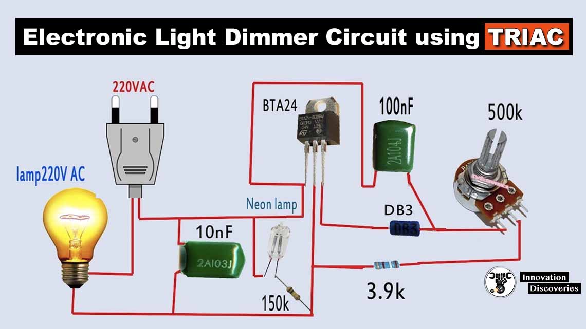
Light Dimmer Circuit Using Triac
This light dimmer circuit is built with various electrical and Electronic components like resistors R1=68 kilo-ohms, R2=280 kilo-ohms and R3=10 kilo-ohms, Variable resistors VR1=100 kilo-ohms and VR2=200 kilo-ohms, Capacitors C1, C2, and C3=0.33 uF/400V, TRIAC is BT136 and DIAC is ER900.
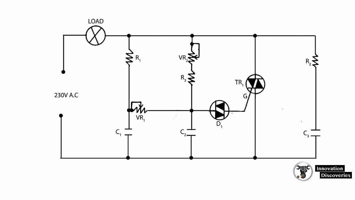
The basic circuit of light dimmer using TRIAC is shown below, and this circuit depends on phase control.
The variable resistor VR1 plays as a main controller in the light dimmer circuit.
The capacitor ‘C2’ in the circuit below gets charged from the mains supply.
In the circuit, variable resistor VR1 and D1 DIAC are used to Control the brightness of the lower level.
To overcome the interface problem, R2 & C3 are used.
Here in this light dimmer circuit, without any change, DIAC can be replaced by the BC148 transistor.
When the transistor is used instead of DIAC, Then the base terminal of the transistor not connected and remaining terminals Like emitter and collector are connected without the help of polarity.
In this circuit, a diode is used as a DIAC.
Working of light Dimmers
Modern light dimmers operate by adjusting the service cycle of the AC voltage that is applied to the operated lights.
Then the light bulb will appear with less intensity when it gets the full AC voltage.
Because it gets the low power to heat the filament.
These light dimmers use the brightness knob to control at what point
Each cycle to switch the light ON and OFF.
Typical light dimmers are built with thyristors and the fixed time When the thyristor is enabled practically to the zero crossings of the AC power to decide the power level.
When the thyristor activates then it keeps directing until the current passing through when it goes to zero.
The phase can be changed when the TRIAC is activated, you change the duty cycle and thus the brightness of the light.
Here is the sine waveform of the normal AC power get from the receptacle.
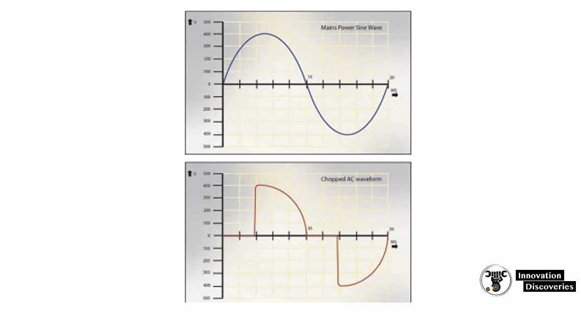
As you can observe, by changing the turn ON point, The power flowing to the bulb is variable and hence the o/p of the light can be controlled.
The benefit of thyristor over variable resistors is that they waste Very little power either they are ON or OFF.
Typically, thyristor causes a 1 to 1.5 V voltage drop when it passes the load current.
This is all about what is TRIAC, light dimmer circuit using TRIAC, working of light dimmers.
We hope that you have got a better understanding of this concept.
Furthermore, any queries regarding this topic or power electronics project ideas, Please give your valuable suggestions by commenting in the comment section below.
Here is a question for you, what are the applications of light dimmers?
See More – Circuit Diagram
One Comment