Introduction
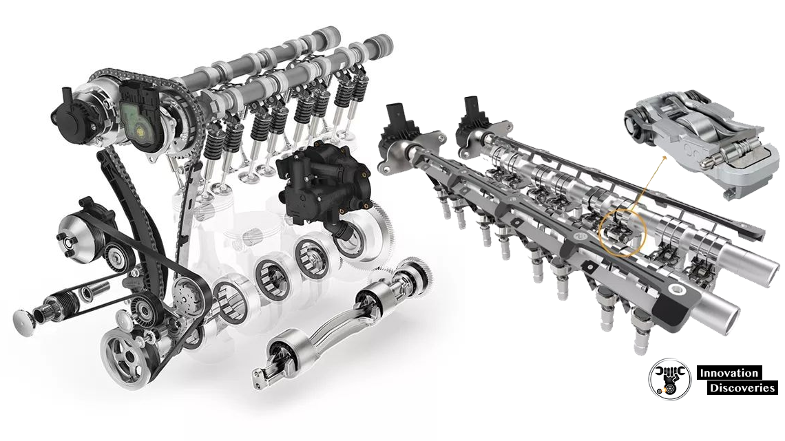
The main function of the valve train, as indicated by its name, is to control the opening and closing of the valves and, for older models, the fuel output of the injectors.
Most of the heavy-duty diesel engines we work with are 4 valve engines, meaning there are four valves in each cylinder: 2 intakes and 2 exhaust. The valve train uses different components based on the type, push on or lift up from the valves, allowing air into and out from the cylinder.
In the middle of all the valves is the injector, which will be pushed down on to inject fuel into the cylinder. All of the timing for this process is incredibly precise.
Newer engines use electrical signals to cue the injector, rather than the mechanical valve train, which makes that process even more precise.
Most new engines have overhead cam assemblies. Other designs locate the camshaft lower in the engine and use push rods to move valve assemblies. The camshaft is rotated by a timing belt, timing chain or direct gear.
VALVE TRAIN COMPONENTS
The valve train can have many components. The following are the most common components in the valve train. Depending on the type of engine, there may be varying quantities of the parts listed below or the engine may not contain all of the parts listed.
1. Camshaft
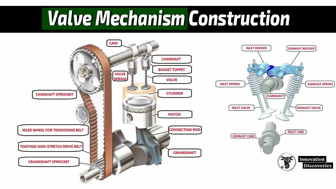
The camshaft is a vital component in the engine’s valve train system. It is a long, cylindrical rod with multiple egg-shaped lobes along its length. These lobes, also known as cams, are positioned at precise intervals to control the timing and lift of the valves. The shape and size of the lobes determine how long and how far the valves will open, directly affecting the engine’s performance.
Function:
The primary function of the camshaft is to convert the rotational motion of the crankshaft into the linear motion needed to open and close the engine’s valves. As the camshaft rotates, the lobes push against camshaft followers (lifters or tappets), which then transfer this motion to the valves through various components such as push rods and rocker arms.
Placement:
- Overhead Camshaft (OHC) Engines: In OHC engines, the camshaft is located in the cylinder head, directly above the valves. This placement allows for more direct control of the valves, reducing the number of components required and improving engine efficiency.
- Pushrod (OHV) Engines: In OHV engines, the camshaft is located in the engine block. The motion from the camshaft is transferred to the valves through push rods and rocker arms. This design is simpler and more compact but can be less efficient at high RPMs compared to OHC designs.
Types of Camshafts:
- Single Overhead Cam (SOHC):
- A single camshaft per cylinder bank.
- Controls both intake and exhaust valves.
- Simpler design, suitable for engines with fewer valves per cylinder.
- Double Overhead Cam (DOHC):
- Two camshafts per cylinder bank.
- One camshaft controls the intake valves, and the other controls the exhaust valves.
- Allows for better valve timing and higher performance, suitable for engines with four valves per cylinder.
Camshaft Profiles:
The profile of the camshaft lobes is critical for engine performance. The shape of the lobes determines:
- Valve Lift: The distance the valve is lifted off its seat.
- Valve Duration: The length of time the valve remains open.
- Valve Timing: The specific timing of valve opening and closing relative to the position of the crankshaft.
Performance engines often have camshafts with more aggressive profiles, providing higher lift and longer duration to allow more air and fuel into the cylinders, enhancing power output.
Materials:
Camshafts are typically made from hardened steel or cast iron to withstand the high-stress environment of the engine. Advanced manufacturing techniques such as billet machining and heat treatment are used to ensure durability and performance.
Maintenance:
Regular maintenance and inspection of the camshaft are crucial for engine health. Signs of wear or damage, such as pitting or scoring on the lobes, can lead to poor valve timing and reduced engine performance. Lubrication is essential to minimize friction and wear, with oil passages often integrated into the camshaft design to ensure proper lubrication of the lobes and bearings.
In summary, the camshaft is a critical component that plays a central role in controlling the timing and operation of an engine’s valves, directly influencing the engine’s performance and efficiency. Its design, placement, and maintenance are key factors in ensuring optimal engine function.
2. Camshaft Followers
Camshaft followers, also known as lifters or tappets, are crucial components in the engine’s valve train system. They are located between the camshaft and the push rods or rocker arms (depending on the engine design). These components follow the camshaft lobes as the camshaft rotates, converting the rotational motion into linear motion needed to operate the valves.
Function:
The primary function of camshaft followers is to translate the camshaft’s rotational movement into vertical motion that can be used to open and close the engine’s valves. As the camshaft rotates, the lobes push against the camshaft followers, causing them to move up and down. This movement is then transferred to the push rods or directly to the rocker arms, which then act on the valves.
Types of Camshaft Followers:
- Flat Tappet Lifters:
- Description: Have a flat surface that contacts the camshaft lobe.
- Function: Simple design, common in older engines.
- Advantages: Lower manufacturing cost.
- Disadvantages: Higher friction and wear, requiring more frequent lubrication and maintenance.
- Roller Lifters:
- Description: Feature a small roller or wheel that contacts the camshaft lobe.
- Function: The roller reduces friction between the camshaft and the follower.
- Advantages: Lower friction and wear, allowing for higher engine speeds and improved efficiency.
- Disadvantages: More complex and expensive to manufacture.
- Hydraulic Lifters:
- Description: Can be either flat tappet or roller lifters but include an internal hydraulic mechanism.
- Function: Automatically adjust to maintain zero valve clearance, reducing valve train noise and maintenance.
- Advantages: Self-adjusting, quieter operation, reduced maintenance.
- Disadvantages: Can be sensitive to oil quality and pressure, slightly heavier than solid lifters.
- Solid Lifters:
- Description: Also known as mechanical lifters.
- Function: Require manual adjustment to maintain proper valve clearance.
- Advantages: More precise control over valve timing, suitable for high-performance engines.
- Disadvantages: Require regular maintenance and adjustment, noisier operation.
Placement:
- In Pushrod Engines (OHV): Camshaft followers are located in the engine block. The motion from the followers is transferred to the push rods, which then actuate the rocker arms and valves.
- In Overhead Cam (OHC) Engines: Followers are often integrated directly into the cylinder head and may act directly on the valves or through rocker arms.
Materials:
Camshaft followers are typically made from hardened steel or other durable materials to withstand the high-stress environment and constant contact with the camshaft lobes. Roller lifters may incorporate additional materials such as needle bearings for the roller wheel.
Maintenance:
Regular inspection and maintenance of camshaft followers are essential for engine performance and longevity. Signs of wear or damage, such as pitting or scoring, can lead to poor valve timing and reduced engine efficiency. Proper lubrication is crucial to minimize friction and wear, and ensuring the use of high-quality oil can prolong the lifespan of camshaft followers.
Advantages and Disadvantages:
- Advantages:
- Translates rotational motion into linear motion efficiently.
- Reduces wear on camshaft lobes.
- Various types available for different engine performance needs.
- Disadvantages:
- Can wear out over time, requiring replacement.
- Hydraulic lifters can be sensitive to oil quality and pressure.
- Solid lifters require regular adjustment.
In summary, camshaft followers are integral components that ensure the proper operation of the engine’s valve train. They come in various types, each with its own set of advantages and disadvantages, catering to different engine designs and performance requirements. Proper maintenance and lubrication are key to their efficient operation and longevity.
3. Push Rods
Push rods are slender, cylindrical components in an engine’s valve train that transfer motion from the camshaft followers (lifters) to the rocker arms, which then open and close the valves. They are a critical link in the chain of components that control valve operation, especially in overhead valve (OHV) or pushrod engines.
Function:
The primary function of push rods is to transmit the lifting force generated by the camshaft lobes, via the lifters, to the rocker arms. As the camshaft rotates, its lobes push against the camshaft followers. This movement is then transferred vertically through the push rods to the rocker arms, which pivot to open the engine’s intake and exhaust valves.
Placement:
Push rods are typically used in OHV engines, where the camshaft is located in the engine block. They extend vertically from the camshaft followers in the engine block up to the rocker arms in the cylinder head.
Characteristics:
- Length and Diameter:
- Push rods must be precisely measured to ensure proper valve timing and operation. Incorrect length can lead to improper valve timing, causing engine performance issues.
- The diameter of push rods can vary depending on the engine design and required strength. Thicker push rods are often used in high-performance engines to handle greater stresses.
- Hollow vs. Solid:
- Some push rods are hollow to reduce weight and allow for oil passage to the rocker arms and valve tips. This design helps with lubrication and cooling.
- Solid push rods are simpler and more robust but lack the internal lubrication capability.
Materials:
Push rods are usually made from high-strength steel or chrome-molybdenum alloys. These materials provide the necessary durability and resistance to wear and bending under high-stress conditions. Some high-performance applications may use lightweight materials like aluminum or composite materials to reduce weight and improve engine response.
Maintenance:
Regular inspection and maintenance of push rods are crucial to ensure optimal engine performance. Key maintenance considerations include:
- Checking for Wear and Damage: Push rods can wear out or become bent over time, especially under high-performance or heavy-duty use. Signs of wear or damage include bending, scoring, or pitting.
- Proper Lubrication: Ensuring that push rods are adequately lubricated helps reduce friction and wear. Engines with hollow push rods rely on a steady flow of oil for proper lubrication and cooling.
Advantages and Disadvantages:
- Advantages:
- Simple and effective design for transferring motion from camshaft followers to rocker arms.
- Suitable for a wide range of engine applications, from everyday vehicles to high-performance engines.
- Robust and durable, capable of withstanding high-stress environments.
- Disadvantages:
- Adds weight and complexity to the valve train, which can limit high-RPM performance compared to overhead cam (OHC) designs.
- Requires precise length and alignment to ensure proper valve operation.
- Increases the overall height of the engine, which can impact engine design and packaging.
Applications:
Push rods are commonly found in:
- OHV (Pushrod) Engines: Most commonly used in American V8 engines and other traditional engine designs.
- Diesel Engines: Often used in heavy-duty diesel engines for trucks and industrial applications.
- High-Performance Engines: In some performance applications, reinforced push rods are used to handle increased power and stress.
In summary, push rods are essential components in pushrod engine designs, effectively transmitting motion from the camshaft to the valves. Their design, material, and maintenance are critical for ensuring reliable and efficient engine operation. Properly maintained push rods contribute to optimal valve timing, engine performance, and longevity.
4. Rocker Arms
Rocker arms are pivotal components in an engine’s valve train system. They act as levers that transfer the motion from the camshaft followers or push rods to the valves, facilitating their opening and closing. Rocker arms come in various designs, tailored to different engine types and performance requirements.
Function:
The primary function of rocker arms is to translate the upward motion from the push rods or camshaft followers into a downward force that opens the intake and exhaust valves. As the camshaft rotates, its lobes push the camshaft followers or lifters, which in turn push the push rods. This motion is then transferred to the rocker arms, causing them to pivot and press down on the valve stems, opening the valves. When the camshaft lobe rotates away, the valve spring closes the valve, returning the rocker arm to its original position.
Types of Rocker Arms:
- Stamped Steel Rocker Arms:
- Description: Made from a single piece of stamped steel.
- Function: Common in production engines due to their low cost and adequate performance for most applications.
- Advantages: Lightweight, inexpensive, and sufficient for many stock engine applications.
- Disadvantages: Limited strength and durability under high-performance conditions.
- Roller Rocker Arms:
- Description: Feature a roller bearing at the contact point with the valve stem.
- Function: Reduces friction and wear, allowing for smoother and more efficient valve operation.
- Advantages: Increased durability, reduced friction, and better performance, especially at high RPMs.
- Disadvantages: More expensive and complex than stamped steel rockers.
- Full Roller Rocker Arms:
- Description: Have roller bearings at both the valve tip and the pivot point.
- Function: Minimize friction throughout the entire range of motion.
- Advantages: Maximum reduction in friction and wear, ideal for high-performance and racing applications.
- Disadvantages: Highest cost and complexity.
- Shaft-Mounted Rocker Arms:
- Description: Mounted on a shaft rather than individual studs.
- Function: Provide more stable and precise valve operation, often used in high-performance and racing engines.
- Advantages: Improved stability, reduced deflection, and better performance under extreme conditions.
- Disadvantages: Higher cost and complexity compared to stud-mounted rockers.
Placement:
- OHV (Overhead Valve) Engines: Rocker arms are typically mounted on studs or a shaft in the cylinder head, above the valves. They receive motion from the push rods.
- OHC (Overhead Camshaft) Engines: Rocker arms may be integrated directly into the camshaft system, with the camshaft lobes acting directly on them or through a cam follower.
Materials:
Rocker arms are usually made from materials that provide a good balance of strength, durability, and weight. Common materials include:
- Stamped Steel: Cost-effective and adequate for standard applications.
- Aluminum: Lightweight, used in many performance applications.
- Chromoly Steel: Strong and durable, used in high-performance and racing engines.
- Titanium: Extremely lightweight and strong, used in top-tier racing applications.
Maintenance:
Regular inspection and maintenance of rocker arms are crucial for ensuring optimal engine performance and longevity. Key maintenance considerations include:
- Checking for Wear and Damage: Inspect for signs of wear, cracks, or damage that can affect valve timing and operation.
- Proper Lubrication: Ensure rocker arms are adequately lubricated to minimize friction and wear.
- Valve Clearance Adjustment: In engines with adjustable rocker arms, regularly check and adjust valve clearance to maintain proper valve operation.
Advantages and Disadvantages:
- Advantages:
- Essential for converting camshaft motion into valve operation.
- Different designs available to suit various performance requirements.
- Roller and full roller designs reduce friction and wear, improving efficiency and performance.
- Disadvantages:
- Can be a source of wear and require regular maintenance.
- Higher performance designs can be expensive and complex.
- In OHV engines, rocker arms contribute to a more complex and taller engine design compared to OHC engines.
Applications:
Rocker arms are found in a wide range of engine types, including:
- Standard Production Engines: Typically use stamped steel rocker arms for cost-effectiveness.
- High-Performance and Racing Engines: Often use roller or full roller rocker arms for improved performance and durability.
- Diesel Engines: Use robust rocker arms designed to handle high stresses and long service life.
In summary, rocker arms are pivotal in an engine’s valve train, translating camshaft motion into valve operation. They come in various designs and materials to meet different performance and durability requirements. Proper maintenance and selection of the right type of rocker arms are crucial for ensuring efficient and reliable engine operation.
5. Rocker Shafts
Rocker shafts are cylindrical shafts that serve as the pivot points for rocker arms in an engine’s valve train system. They provide the necessary support and alignment for the rocker arms to operate smoothly and efficiently. Rocker shafts are integral to the stability and functionality of the valve train, particularly in engines with shaft-mounted rocker arms.
Function:
The primary function of rocker shafts is to provide a stable and precise pivot point for the rocker arms. As the rocker arms pivot to open and close the valves, the rocker shafts ensure that this motion is consistent and accurately aligned. They also play a crucial role in distributing the force applied by the rocker arms and maintaining proper valve timing.
Placement:
Rocker shafts are typically mounted in the cylinder head of the engine, running parallel to the camshaft. They support the rocker arms at their pivot points, allowing the arms to move up and down as they actuate the valves.
Characteristics:
- Design:
- Solid or Hollow: Rocker shafts can be either solid or hollow. Hollow shafts are often used to reduce weight and allow for internal oil passages.
- Mounting Points: Rocker shafts have mounting points that secure them to the cylinder head, ensuring they remain in place during engine operation.
- Oil Passages:
- Some rocker shafts are designed with internal oil passages to deliver lubrication directly to the rocker arms and other valve train components. This design helps reduce friction and wear, improving the overall efficiency and lifespan of the valve train.
Materials:
Rocker shafts are typically made from high-strength materials such as hardened steel or chrome-molybdenum alloys. These materials provide the necessary durability to withstand the high forces and stresses encountered during engine operation. For high-performance applications, lightweight materials such as titanium may be used to reduce weight and improve engine response.
Maintenance:
Regular inspection and maintenance of rocker shafts are crucial for ensuring the proper operation of the valve train. Key maintenance considerations include:
- Checking for Wear and Damage: Inspect the rocker shafts for signs of wear, scoring, or damage that could affect the alignment and movement of the rocker arms.
- Proper Lubrication: Ensure that the rocker shafts and associated components are adequately lubricated to minimize friction and wear.
- Alignment and Secure Mounting: Verify that the rocker shafts are securely mounted and properly aligned to maintain consistent valve timing and operation.
Advantages and Disadvantages:
- Advantages:
- Provide a stable pivot point for rocker arms, ensuring accurate valve operation.
- Help distribute the forces applied by the rocker arms, reducing wear on individual components.
- Can incorporate internal oil passages for improved lubrication.
- Disadvantages:
- Can add complexity to the valve train system, particularly in engines with multiple rocker shafts.
- Require precise manufacturing and alignment to ensure proper operation.
Applications:
Rocker shafts are commonly used in:
- OHV (Overhead Valve) Engines: Typically found in traditional American V8 engines and other pushrod designs.
- OHC (Overhead Camshaft) Engines: Used in some high-performance and racing engines where shaft-mounted rocker arms provide improved stability and precision.
- Diesel Engines: Often used in heavy-duty diesel engines for trucks and industrial applications due to their robust design and durability.
Summary:
In summary, rocker shafts are essential components in an engine’s valve train, providing the necessary support and alignment for the rocker arms. Their design, material, and maintenance are critical for ensuring the efficient and reliable operation of the valve train. Properly maintained rocker shafts contribute to optimal valve timing, engine performance, and longevity.
6. Valve Bridges
Valve bridges, also known as valve yokes, are components used in engines to actuate multiple valves simultaneously using a single rocker arm. They are designed to distribute the force from the rocker arm evenly across multiple valve stems, ensuring synchronized operation of the valves.
Function:
The primary function of valve bridges is to allow a single rocker arm to open and close multiple valves at the same time. This is particularly useful in engines with multi-valve configurations, where more than one intake or exhaust valve per cylinder needs to be operated in unison. Valve bridges ensure that both valves open and close together, maintaining proper timing and airflow.
Placement:
Valve bridges are typically positioned between the rocker arm and the valve stems. They sit atop the valve stems and connect them, allowing the force from the rocker arm to be distributed evenly across the connected valves.
Characteristics:
- Design:
- Yoke Shape: Valve bridges often have a yoke shape that fits over two valve stems, with a central contact point where the rocker arm applies force.
- Precision Fit: They are designed to fit precisely over the valve stems to ensure even force distribution and synchronized valve movement.
- Material:
- Valve bridges are usually made from high-strength materials such as steel or aluminum to withstand the forces applied during valve operation. The material needs to be durable and resistant to wear.
- Oil Passages:
- Some valve bridges are designed with internal oil passages or channels to facilitate lubrication of the valve stems and reduce friction.
Maintenance:
Regular inspection and maintenance of valve bridges are crucial for ensuring proper valve operation and longevity. Key maintenance considerations include:
- Checking for Wear and Damage: Inspect valve bridges for signs of wear, cracks, or other damage that could affect their performance.
- Ensuring Proper Fit: Verify that valve bridges fit securely over the valve stems and are properly aligned.
- Lubrication: Ensure adequate lubrication to minimize friction and wear on the valve stems and bridge.
Advantages and Disadvantages:
- Advantages:
- Allows a single rocker arm to control multiple valves, simplifying the valve train design.
- Ensures synchronized operation of multiple valves, improving engine performance and efficiency.
- Distributes force evenly across multiple valves, reducing stress on individual components.
- Disadvantages:
- Adds complexity to the valve train assembly, requiring precise manufacturing and alignment.
- Potential for increased wear if not properly lubricated or maintained.
Applications:
Valve bridges are commonly used in:
- Multi-Valve Engines: Especially in high-performance and modern engines with multiple intake and exhaust valves per cylinder.
- Heavy-Duty Diesel Engines: Where robust valve train components are required to handle high stresses and prolonged operation.
- High-Performance Engines: Where synchronized valve operation is critical for maximizing airflow and engine efficiency.
Summary:
Valve bridges are essential components in multi-valve engine designs, allowing a single rocker arm to operate multiple valves simultaneously. Their design, material, and proper maintenance are crucial for ensuring synchronized valve operation, optimal engine performance, and longevity. Properly maintained valve bridges contribute to efficient and reliable valve train operation, especially in high-performance and heavy-duty applications.
7. Valves
Valves are critical components in an internal combustion engine, responsible for controlling the flow of air and fuel into the cylinders and the expulsion of exhaust gases. Each cylinder in an engine typically has at least one intake valve and one exhaust valve, although modern high-performance engines may have multiple intake and exhaust valves per cylinder.
Function:
The primary function of valves is to regulate the timing and quantity of air-fuel mixture entering the combustion chamber (intake valves) and to allow exhaust gases to exit the combustion chamber (exhaust valves) after combustion. This process is crucial for the engine’s breathing and overall efficiency.
Types:
- Intake Valves:
- Function: Allow the air-fuel mixture to enter the combustion chamber.
- Characteristics: Typically larger than exhaust valves to maximize airflow into the cylinder.
- Exhaust Valves:
- Function: Permit exhaust gases to exit the combustion chamber after the combustion process.
- Characteristics: Designed to withstand high temperatures and pressures from the exhaust gases.
Components:
- Valve Head:
- Description: The larger, flat part of the valve that seals against the valve seat in the cylinder head.
- Function: Provides the sealing surface that opens to allow gases to pass and closes to seal the combustion chamber.
- Valve Stem:
- Description: The long, slender part of the valve that extends into the cylinder head.
- Function: Guides the valve’s movement within the valve guide and transmits force from the valve train to the valve head.
- Valve Face:
- Description: The angled surface on the valve head that mates with the valve seat.
- Function: Creates a tight seal when the valve is closed, preventing leakage of gases.
- Valve Seat:
- Description: The corresponding surface in the cylinder head where the valve face seals.
- Function: Provides a durable surface for the valve to seal against, ensuring no gases escape during combustion.
- Valve Keepers (or Collets):
- Description: Small, semi-circular pieces that lock the valve spring retainer to the valve stem.
- Function: Secure the valve spring retainer in place, holding the valve assembly together.
- Valve Guides:
- Description: Cylindrical sleeves in the cylinder head through which the valve stems move.
- Function: Guide the valve stems, ensuring smooth and precise movement of the valves.
- Valve Springs:
- Description: Coiled springs that fit around the valve stem.
- Function: Provide the necessary force to close the valves after they have been opened by the camshaft or rocker arm.
Materials:
Valves are typically made from high-strength, heat-resistant materials to withstand the extreme conditions inside an engine. Common materials include:
- Steel Alloys: Used for durability and heat resistance.
- Titanium: Used in high-performance engines for its lightweight and high strength.
- Sodium-Filled Valves: Used in some exhaust valves to improve heat dissipation.
Maintenance:
Regular inspection and maintenance of valves are crucial for ensuring optimal engine performance and longevity. Key maintenance considerations include:
- Checking for Wear and Damage: Inspect valve faces, stems, and seats for signs of wear, pitting, or burning.
- Valve Clearance Adjustment: Ensure proper valve clearance (or lash) to maintain efficient operation and prevent valve damage.
- Lubrication: Ensure adequate lubrication to minimize friction and wear on valve stems and guides.
Advantages and Disadvantages:
- Advantages:
- Essential for controlling airflow and exhaust in the engine.
- Available in various designs and materials to suit different engine types and performance requirements.
- Properly functioning valves contribute to efficient combustion and engine performance.
- Disadvantages:
- Subject to wear and damage from high temperatures and pressures.
- Require precise manufacturing and maintenance to ensure proper operation.
- Misadjusted or damaged valves can lead to poor engine performance and potential engine damage.
Applications:
Valves are used in all types of internal combustion engines, including:
- Automotive Engines: Found in gasoline and diesel engines in cars, trucks, and motorcycles.
- Aviation Engines: Used in aircraft engines for precise control of airflow and exhaust.
- Industrial Engines: Found in engines powering generators, pumps, and other industrial equipment.
- High-Performance Engines: Used in racing and high-performance applications where efficiency and power are critical.
Summary:
Valves are crucial components in an internal combustion engine, controlling the flow of air-fuel mixture and exhaust gases. They are made from high-strength materials and require regular maintenance to ensure efficient and reliable engine operation. Properly functioning valves are essential for optimal engine performance, efficiency, and longevity.
8. Valve Springs
Valve springs are components in an internal combustion engine’s valve train system designed to control the opening and closing of the valves. They apply the necessary force to close the valves after they have been opened by the camshaft or rocker arm. Valve springs are essential for maintaining proper valve timing and ensuring efficient engine operation.
Function:
The primary function of valve springs is to:
- Close the Valve: Provide the force needed to return the valve to its closed position after it has been opened.
- Maintain Valve Contact: Keep the valve seated properly against the valve seat during engine operation to prevent leakage and ensure a tight seal.
- Absorb Impact: Cushion the impact of the valve closing, reducing the stress and potential damage to the valve train components.
Types:
- Compression Springs:
- Description: The most common type of valve spring, which compresses when the valve is opened and expands when the valve closes.
- Characteristics: Typically used in most automotive engines.
- Dual Springs:
- Description: Consists of two springs of different sizes, one inside the other.
- Characteristics: Provides greater control over valve movement, reduces valve float, and is often used in high-performance engines.
- Beehive Springs:
- Description: Springs with a tapered shape resembling a beehive.
- Characteristics: Designed to reduce the mass of the spring, improve high-RPM performance, and minimize valve float.
- Tapered Springs:
- Description: Springs with a gradually decreasing diameter along their length.
- Characteristics: Provides a progressive spring rate, offering a balance between low-RPM and high-RPM performance.
Components:
- Spring Coil:
- Description: The helical wire wound into a coil shape.
- Function: Provides the necessary force to close the valve and maintain valve contact.
- Spring Seat:
- Description: The surface where the bottom end of the valve spring rests.
- Function: Ensures proper alignment and stability of the spring.
- Spring Retainer:
- Description: A component that holds the top end of the valve spring in place.
- Function: Keeps the spring securely positioned and ensures proper alignment with the valve stem.
- Spring Cap:
- Description: A cap that covers the top end of the valve spring.
- Function: Provides additional support and protection for the valve spring.
Materials:
Valve springs are typically made from high-strength materials to withstand the forces and stresses encountered during engine operation. Common materials include:
- High-Carbon Steel: Provides good strength and durability for standard applications.
- Chrome-Silicon Steel: Offers higher tensile strength and fatigue resistance, often used in performance applications.
- Titanium: Used in high-performance engines for its lightweight and high strength.
Maintenance:
Regular inspection and maintenance of valve springs are crucial for ensuring proper engine operation. Key maintenance considerations include:
- Checking for Wear and Fatigue: Inspect the springs for signs of wear, cracks, or deformation. Replace any springs that show signs of fatigue or damage.
- Measuring Spring Pressure: Ensure that the spring pressure is within specifications to maintain proper valve operation and avoid valve float.
- Inspecting Retainers and Seats: Check the spring retainers and seats for wear or damage that could affect the spring’s performance.
Advantages and Disadvantages:
- Advantages:
- Ensures proper valve closure and maintains valve timing.
- Available in various designs to suit different engine types and performance requirements.
- Helps absorb impact and reduce stress on the valve train components.
- Disadvantages:
- Subject to wear and fatigue over time, requiring periodic inspection and replacement.
- Incorrectly adjusted or worn springs can lead to poor engine performance and potential damage.
Applications:
Valve springs are used in all types of internal combustion engines, including:
- Automotive Engines: Found in gasoline and diesel engines in cars, trucks, and motorcycles.
- High-Performance Engines: Used in racing and performance applications where precise valve control is crucial.
- Industrial Engines: Used in engines powering generators, pumps, and other industrial equipment.
Summary:
Valve springs are essential components in an engine’s valve train system, responsible for closing the valves and maintaining proper valve timing. They come in various designs and materials to suit different engine requirements and performance levels. Regular inspection and maintenance are crucial to ensure the proper operation and longevity of valve springs, contributing to optimal engine performance and efficiency.
9. Timing Belt
The timing belt is a crucial component in an internal combustion engine, responsible for synchronizing the rotation of the crankshaft and camshaft(s). This synchronization ensures that the engine’s valves open and close at the correct times relative to the position of the pistons, which is essential for efficient engine operation and preventing engine damage.
Function:
The primary functions of the timing belt are to:
- Synchronize Camshaft and Crankshaft: Ensure that the camshaft(s) and crankshaft rotate in harmony, so the valves open and close at the correct times.
- Maintain Engine Timing: Keep the engine’s timing precise, which is critical for optimal performance, fuel efficiency, and emissions control.
- Drive Other Components: In some engine designs, the timing belt also drives other components such as the water pump, oil pump, or balance shafts.
Components:
- Belt Teeth:
- Description: The inner surface of the timing belt features cogged or toothed profiles.
- Function: Engage with the corresponding sprockets or gears on the camshaft and crankshaft, transferring rotational motion accurately.
- Belt Material:
- Description: Typically made from a combination of rubber and reinforcing fibers (such as fiberglass or steel).
- Function: Provides the flexibility and strength needed to handle the stresses of engine operation while ensuring long-term durability.
- Belt Tensioner:
- Description: A spring-loaded or hydraulic component that maintains proper tension in the timing belt.
- Function: Keeps the timing belt tight and properly aligned to prevent slipping or jumping of teeth.
- Idler Pulleys:
- Description: Pulley components that guide the timing belt around various engine parts.
- Function: Ensure smooth operation and proper routing of the timing belt.
Types:
- Rubber Timing Belts:
- Description: Made from reinforced rubber with embedded fibers.
- Characteristics: Commonly used in many engines for their flexibility and cost-effectiveness.
- Kevlar-Reinforced Timing Belts:
- Description: Incorporate Kevlar fibers for increased strength and durability.
- Characteristics: Used in high-performance and heavy-duty applications for better resistance to stretching and wear.
- Silent Timing Belts:
- Description: Designed to reduce noise generated during engine operation.
- Characteristics: Often used in vehicles where noise reduction is a priority.
Maintenance:
Regular maintenance and inspection of the timing belt are crucial to avoid engine damage. Key maintenance considerations include:
- Inspection for Wear: Check the belt for signs of wear, cracking, or fraying. Replace the timing belt according to the manufacturer’s recommended interval.
- Tension Check: Ensure that the timing belt tension is within specifications to prevent slippage or improper operation.
- Alignment Check: Verify that the timing belt is properly aligned and not rubbing against other engine components.
Advantages and Disadvantages:
- Advantages:
- Precision Timing: Provides accurate synchronization of the camshaft and crankshaft, essential for proper engine operation.
- Cost-Effective: Generally less expensive than timing chains or gears.
- Reduced Noise: Quieter operation compared to timing chains.
- Disadvantages:
- Wear and Replacement: Timing belts wear out over time and require periodic replacement to prevent engine damage.
- Limited Lifespan: Typically needs replacement between 60,000 to 100,000 miles, depending on the engine and driving conditions.
- Potential for Failure: If the timing belt breaks or slips, it can cause severe engine damage, especially in interference engines where the valves and pistons occupy the same space.
Applications:
Timing belts are used in a variety of internal combustion engines, including:
- Automotive Engines: Common in many cars and trucks for their cost-effectiveness and quiet operation.
- Motorcycles: Often used in motorcycle engines for similar reasons.
- Industrial Engines: Found in some industrial engines where precise timing is required.
Summary:
The timing belt is a critical component in an engine’s valve train system, ensuring proper synchronization between the camshaft and crankshaft. It maintains engine timing, drives additional components, and requires regular inspection and maintenance to avoid engine damage. While timing belts offer precise timing and cost-effective operation, they have a limited lifespan and must be replaced periodically to ensure reliable engine performance.
10. Belt Tensioner
The belt tensioner is a component of an engine’s timing belt or serpentine belt system. Its primary role is to maintain the correct tension on the belt to ensure proper operation of the engine’s various accessories and timing mechanisms. A properly tensioned belt is crucial for optimal performance and longevity of the belt and associated engine components.
Function:
The primary functions of the belt tensioner are to:
- Maintain Proper Tension: Keep the timing or serpentine belt at the correct tension to prevent slipping, noise, or premature wear.
- Compensate for Wear: Adjust tension automatically to account for belt stretching and wear over time.
- Prevent Slippage: Ensure that the belt remains properly engaged with the pulleys and sprockets, preventing slippage that can lead to engine performance issues.
Components:
- Tensioner Pulley:
- Description: A pulley mounted on the tensioner assembly that the belt wraps around.
- Function: Guides the belt and provides a surface for the belt to grip, maintaining proper tension.
- Spring Mechanism:
- Description: A coil spring or hydraulic mechanism that applies constant pressure to keep the belt tensioned.
- Function: Provides the necessary force to keep the belt tight and compensates for belt wear and stretching.
- Pivot Point:
- Description: The mounting point where the tensioner assembly is attached to the engine.
- Function: Allows the tensioner to pivot and adjust the belt tension as needed.
- Adjusting Mechanism:
- Description: May be manual or automatic, depending on the design.
- Function: Provides the ability to adjust the tensioner to maintain proper belt tension.
Types:
- Spring-Loaded Tensioners:
- Description: Uses a coil spring to maintain tension.
- Characteristics: Commonly used in many engines for their simplicity and reliability.
- Hydraulic Tensioners:
- Description: Uses a hydraulic piston or cylinder to maintain tension.
- Characteristics: Provides more precise and stable tension control, often found in modern engines.
- Manual Tensioners:
- Description: Requires manual adjustment to set the correct tension.
- Characteristics: Less common, used in older engine designs where manual adjustment is feasible.
Maintenance:
Regular inspection and maintenance of the belt tensioner are crucial for engine reliability. Key maintenance considerations include:
- Inspection for Wear: Check the tensioner pulley for signs of wear, such as cracking or damage. Replace the tensioner if it shows signs of malfunction.
- Tension Check: Ensure the belt is properly tensioned according to the manufacturer’s specifications. Adjust or replace the tensioner if needed.
- Listening for Noise: Listen for unusual noises such as squealing or rattling, which may indicate a problem with the tensioner or belt.
Advantages and Disadvantages:
- Advantages:
- Automatic Adjustment: Provides automatic tension adjustment to maintain proper belt tension.
- Prevents Slippage: Reduces the risk of belt slippage and associated performance issues.
- Improves Belt Life: Helps extend the life of the timing or serpentine belt by maintaining proper tension.
- Disadvantages:
- Wear and Replacement: Tensioners can wear out over time and may require replacement, especially if they fail to maintain proper tension.
- Complexity: Hydraulic tensioners can be more complex and expensive to replace compared to spring-loaded tensioners.
- Potential for Noise: Malfunctioning or worn tensioners can cause noise and affect engine performance.
Applications:
Belt tensioners are used in various engines and systems, including:
- Automotive Engines: Found in many cars and trucks, both in timing belt and serpentine belt systems.
- Motorcycles: Used in motorcycle engines for timing or accessory drive belts.
- Industrial Engines: Found in some industrial engines where belt-driven components are used.
Summary:
The belt tensioner is a vital component that maintains proper tension on the timing or serpentine belt in an engine. It ensures that the belt operates correctly, prevents slippage, and compensates for belt wear. Regular inspection and maintenance of the belt tensioner are essential for ensuring reliable engine performance and extending the life of the belt. While belt tensioners offer automatic tension adjustment and improve belt longevity, they can wear out over time and may require replacement or adjustment to maintain optimal engine operation.
TYPES OF VALVE TRAINS
1. OHV (Overhead Valve) or Pushrod Valve Train
The OHV or pushrod valve train features long rods that transfer motion from the camshaft to the rocker arms, which then open and close the valves. This design is characterized by its mechanical simplicity and compact nature.
Advantages:
- Simplicity: Fewer moving parts lead to a simpler and more robust design.
- Compact Packaging: Often more compact compared to OHC systems.
- Cost-Effective: Generally less expensive to produce and maintain.
Disadvantages:
- Limited RPM Range: The system’s design limits its ability to operate at higher RPMs, making it less suitable for high-performance applications.
- Increased Noise and Friction: The mechanical nature and heavier components can lead to higher noise levels and increased friction.
- Complex Maintenance: Accessing and servicing the camshaft requires significant engine disassembly, increasing maintenance costs and effort.
- Valve Configuration: Primarily suited for two-valve-per-cylinder layouts; incorporating more valves adds complexity and is less common.
Applications:
- Traditional Vehicles: Common in older vehicles, trucks, and some SUVs.
2. OHC (Overhead Cam) Valve Trains
To address the limitations of pushrod systems, the OHC valve train positions the camshaft(s) above the cylinder head, directly operating the valves.
A. Single Overhead Cam (SOHC)
In the SOHC configuration, a single camshaft per bank of cylinders controls both the intake and exhaust valves.
Advantages:
- Improved Performance: Allows for higher RPMs and better engine breathing compared to OHV systems.
- Reduced Noise: Generally quieter operation due to fewer mechanical components.
- Better Timing: Provides more precise control of valve timing.
Disadvantages:
- Complexity: More complex than OHV systems, requiring careful maintenance.
- Valve Configuration: Generally suited for two or three valves per cylinder. Handling four valves per cylinder with SOHC can become complex.
Applications:
- Modern Vehicles: Found in many standard engines that balance performance and cost.
B. Double Overhead Cam (DOHC)
The DOHC valve train features two camshafts per bank of cylinders—one for intake valves and one for exhaust valves. This setup allows for precise control over valve timing and more flexibility in engine design.
Advantages:
- Enhanced Performance: Supports a four-valve-per-cylinder layout, improving engine breathing and performance, particularly at high RPMs.
- Better Combustion: Allows for optimal spark plug positioning in the middle of the cylinder head, enhancing combustion efficiency.
- Variable Valve Timing: Facilitates advanced technologies like variable valve timing (VVT), optimizing performance across different engine speeds.
Disadvantages:
- Increased Complexity: More components can lead to higher manufacturing and maintenance costs.
- Additional Weight: The extra camshaft adds weight to the engine.
Applications:
- High-Performance and Modern Vehicles: Common in performance cars and engines that require precise control and high RPM capabilities.
Conclusion
The valve train is crucial for precise control of engine valves, affecting performance, efficiency, and maintenance. OHV systems offer simplicity and cost benefits but are limited in high-performance applications.
OHC systems, including SOHC and DOHC, provide better performance and flexibility, with DOHC being particularly advantageous for high-performance engines. Understanding these systems is key to optimizing engine performance and maintenance.
Discover More:
Visit Forum
Visit Our Friendly Website




very good website