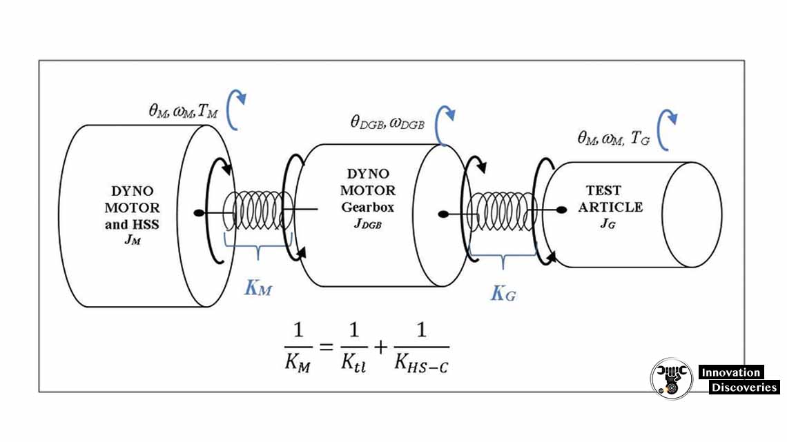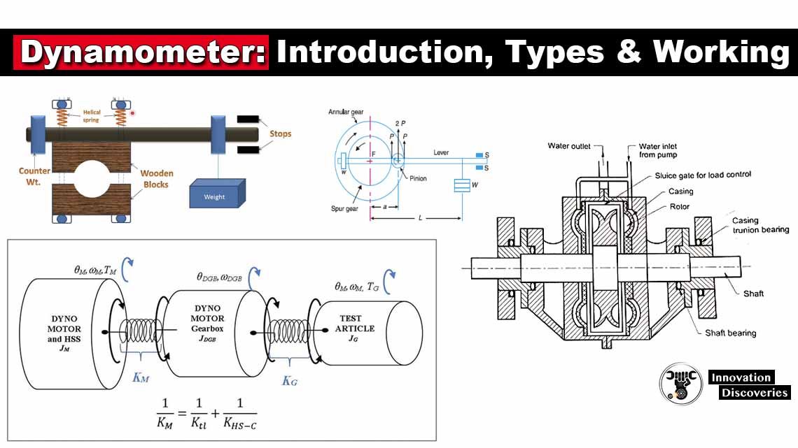
A dynamometer or dyno can be defined as a device that is used to measure torque and the rotational speed of a machine.
This measured data can determine the brake power, speed and other parameters of the rotating machine or an engine.
A dyno, apart from measuring torque and power, can also be used as a test-bed for different types of engine-related activities such as calibration of engine management controllers, deep investigation of combustion behaviour and tribology.
A dynamometer can be classified into two types:
Power absorption dynamometer:
Power Absorption dynamometers measure and absorb the power output of the engine to which they are coupled.
The power absorbed is usually dissipated as heat by some means.
Examples of power absorption dynamometers are Prony brake dynamometer, Rope brake dynamometer, Eddy current dynamometer, Hydraulic dynamometer, etc.
Power transmission dynamometer:
In power transmission dynamometers the power is transmitted to the load coupled to the engine after it is indicated on some scale.
These are also called torque meters.
Classification of absorption dynamometers
Prony brake dynamometer:
It is the simplest form of absorption type dynamometer.
It has two wooden blocks that are placed on a pulley which is fixed on the shaft of the engine whose power is to be measured.
The wooden blocks are clamped together with two sets of bolts and nuts.
To control the speed of the pulley, the pressure is adjusted over a pulley with the help of a helical spring present between the nut and the upper block.
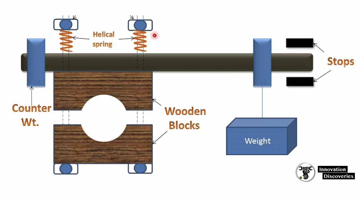
A long lever is attached to the upper block which carries weight on its outer end.
This weight placed on the lever balances the brake when unloaded.
When the brake is to be applied, the suitable weight is loaded on the outer end of the lever and nuts are tightened till the shaft of the engine runs at a constant speed.
The movement because of the weight loaded on the outer end of the lever balances the movement of frictional resistance between the pulley and wooden block.
The power absorbed during friction is converted into heat which is why this dynamometer needs to be cooled down often.
The brake power formula is given by,
Brake power (bp) = 2π NT, where T = Weight applied (W) × distance (l)
Rope brake dynamometer:
This device also measures the brake power and consists of some turns of rope that is wound around the rotating drum fixed on the output shaft.
One end of the rope is connected to the loading device and another end to the spring balance.
The power is absorbed when friction is produced between the rope and the drum.
This type of dynamometer is cheap and can be made quickly.
However, braking power is not accurately measured due to a change in the friction coefficient of the rope with the temperature change.
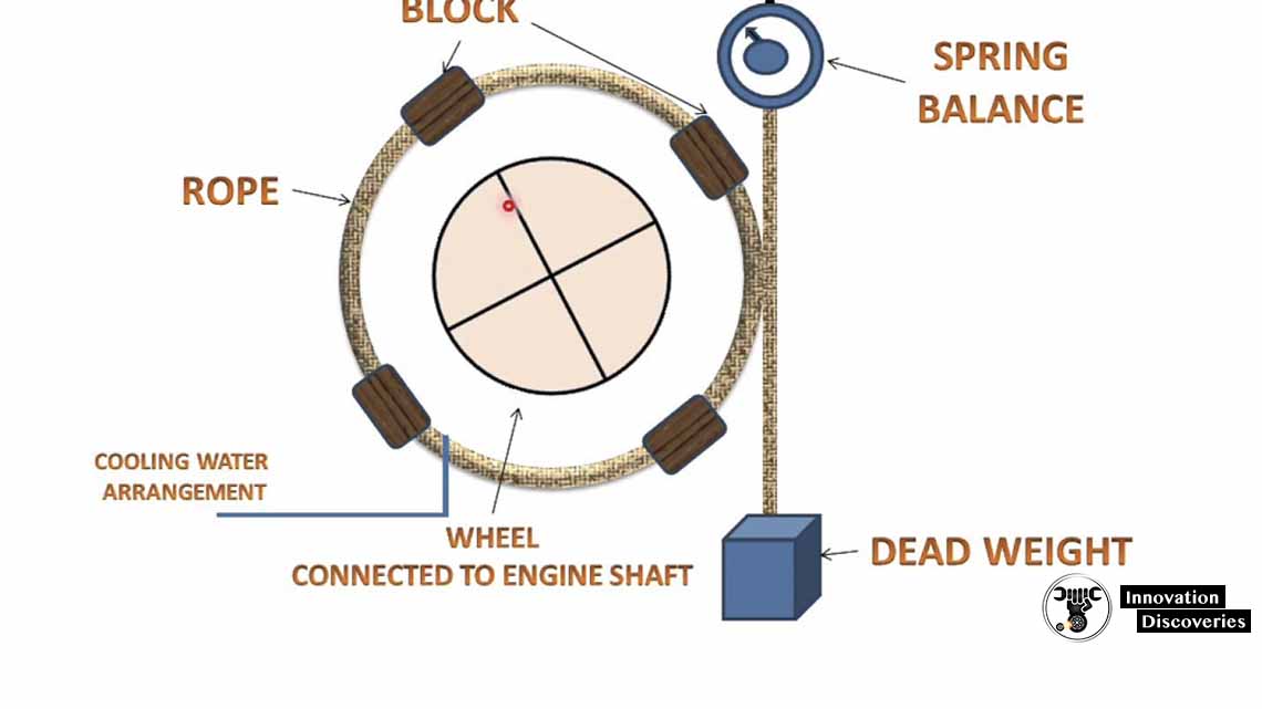
Brake power is given by:
Brake power (bp) = π DN (W − S)
Where D is the diameter of drum brake
W is the weight of the load
S is reading in spring balance.
Eddy current dynamometer:
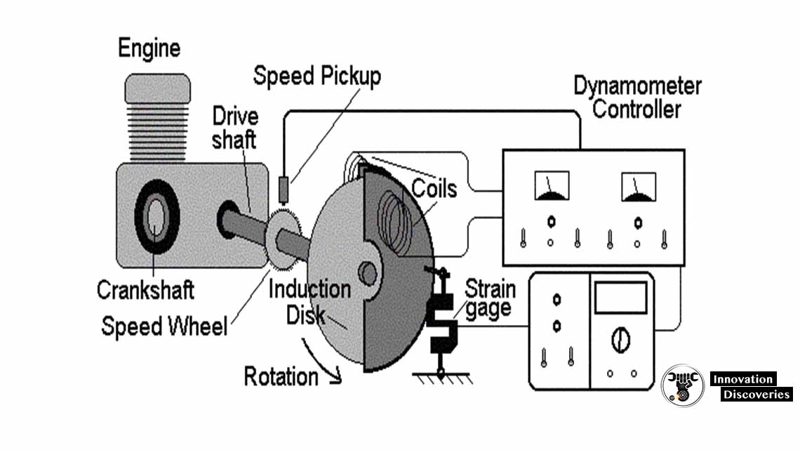
It comprises a stator with some electromagnets and a rotor disc coupled with the engine’s output shaft made of steel or copper.
When the rotor is rotated, an eddy current is produced because of a magnetic flux set up by field current in the electromagnet.
This eddy current is dissipated in generating heat, therefore it needs some cooling arrangements.
The torque is measured with the help of a moment arm just like in other types of absorption dynamometer.
Hydraulic dynamometer:
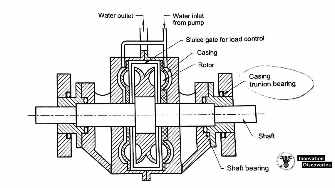
It works on the principle of dissipating heat in fluid friction rather than dry friction.
Its construction is similar to that of the fluid wheel and it consists of an impeller coupled to the output shaft of the engine.
The impeller rotates inside a casing filled with fluid.
Due to the centrifugal force which develops in the outer casing, it tends to rotate along with the impeller but its rotation is restricted by the torque arm that supports weight balance.
Belt transmission dynamometer:
The spring balance system measures the friction generated between the impeller and fluid.
The continuous flow of working fluid carries the heat dissipated in the hydraulic dynamometer.
Moreover, to control the output power in this type of dynamometer, sluice gates can be moved in or out to partially or wholly obstruct the flowing water between the impeller and casing.
Classification of transmission dynamometers:
Epicyclical train dynamometer:
In an epicyclical train dynamometer, between the prime mover and driven, an epicycle gear train is placed to measure the power transmitted.
A spur gear is a key to the engine shaft which rotates in the anti-clockwise direction.
Moreover, an angular gear is keyed to the engine shaft and rotates in the anti-clockwise direction.
In this type of dynamometer, pulleys are linked to the belt passing through two pulleys that are placed on a lever.
This lever carries dead weight at one end and balancing weight at another end.
Torsion dynamometer:
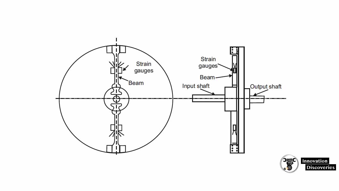
When the power is transmitted through the shaft, there is a twist near the driving end by a small angle relative to the other end.
In such a case, a torsion dynamometer is used that measures the power and angle of twist in the shaft.
