WHAT IS AN OXYGEN SENSOR?
The oxygen sensor (commonly referred to as an “O2 sensor”, as O2 is the chemical formula for oxygen) is mounted in the exhaust manifold of the vehicle to monitor how much-unburned oxygen is in the exhaust as the exhaust exits the engine.
WHAT DOES AN OXYGEN SENSOR DO?
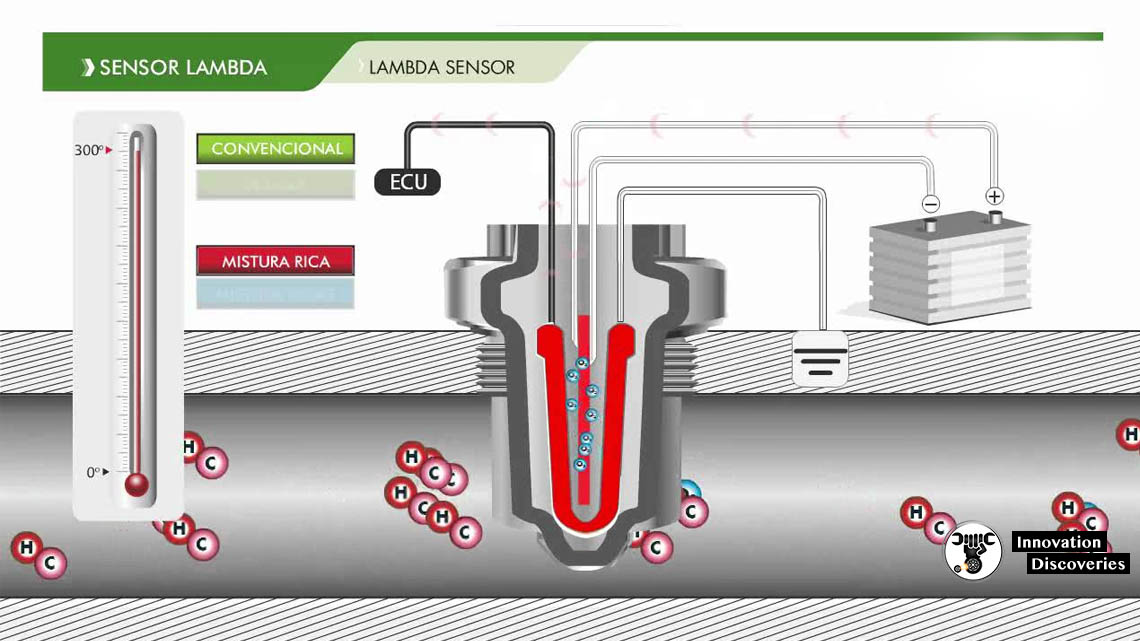
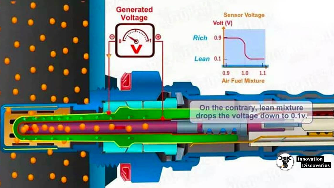
Oxygen sensors work by producing their own voltage when they get hot (approximately 600°F). On the tip of the oxygen sensor that plugs into the exhaust manifold is a zirconium ceramic bulb. The inside and the outside of the bulb is coated with a porous layer of platinum, which serve as the electrodes. The interior of the bulb is vented internally through the sensor body to the outside atmosphere. When the outside of the bulb is exposed to the hot gases of the exhaust, the difference in oxygen levels between the bulb and the outside atmosphere within the sensor causes the voltage to flow through the bulb. If the fuel ratio is lean (not enough fuel in the mixture), the voltage is relatively low — approximately 0.1 volts. If the fuel ratio is rich (too much fuel in the mixture), the voltage is relatively high — approximately 0.9 volts. When the air/fuel mixture is at the stoichiometric ratio (14.7 parts air to 1 part fuel), the oxygen sensor produces 0.45 volts.
WHERE ARE OXYGEN SENSORS LOCATED?
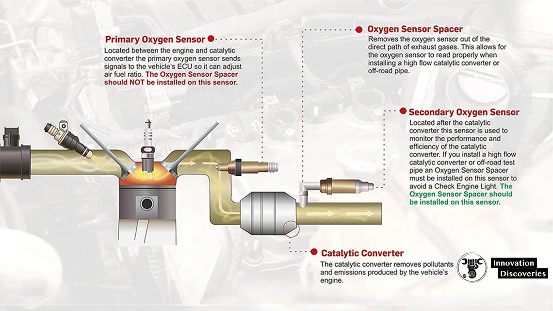
The amount of oxygen sensors a vehicle has varied. Every car made after 1996 is required to have an oxygen sensor upstream and downstream of each catalytic converter. Therefore, while most vehicles have two oxygen sensors, those V6 and V8 engines equipped with dual exhaust have four oxygen sensors — one upstream and downstream of the catalytic converter on each bank of the engine.
1. The Upstream Oxygen Sensor (Oxygen Sensor 1)
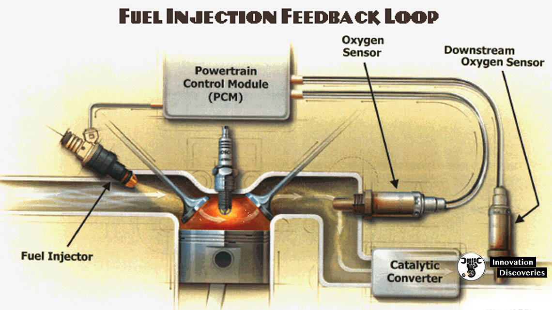
Oxygen sensor 1 is the upstream oxygen sensor in relationship to the catalytic converter. It measures the air-fuel ratio of the exhaust coming out of the exhaust manifold and sends the high and low voltage signals to the powertrain control module in order to regulate the air-fuel mixture. When the powertrain control module receives a low voltage (lean) signal, it compensates by increasing the amount of fuel in the mixture. When the powertrain control module receives a high voltage (rich) signal, it leans the mixture by reducing the amount of fuel it adds to the mixture. The powertrain control module’s use of the input from the oxygen sensor to regulate the fuel mixture is known as a closed feedback control loop. This closed-loop operation results in a constant flip-flop between rich and lean, which allows the catalytic converter to minimize emissions by keeping the overall average ratio of the fuel mixture in proper balance. However, when a cold engine is started, or if an oxygen sensor fails, the powertrain control module enters into open-loop operation. In open-loop operation, the powertrain control module does not receive a signal from the oxygen sensor and orders a fixed rich fuel mixture. Open-loop operation results in increased fuel consumption and emissions. Many newer oxygen sensors contain heating elements to help them get to operating temperature quickly in order to minimize the amount of time spent in open-loop operation.
2. The Downstream Oxygen Sensor (Oxygen Sensor 2)
Oxygen sensor 2 is the downstream oxygen sensor in relationship to the catalytic converter. It measures the air-fuel ratio coming out of the catalytic converter to ensure the catalytic converter is functioning properly. The catalytic converter works to maintain the stoichiometric air-fuel ratio 14.7:1 while the powertrain control module constantly flip-flops between rich and lean air-fuel mixtures due to the input from the upstream oxygen sensor (sensor 1). Therefore, the downstream oxygen sensor (sensor 2) should produce a steady voltage of approximately 0.45 volts.
HOW OXYGEN SENSORS WORK
Step by step guide on how an automotive oxygen sensor works, this article pertains to most vehicles.
Step 1 – An oxygen sensor is an electronic component that is designed to measure levels of oxygen in an automotive engine exhaust system.
Step 2 – Typically, the oxygen sensor is mounted to the exhaust system tube or on the side of a catalytic converter, with the sensor part inside the tube. This measures the oxygen mixture by generating a small amount of electricity due to the difference in atmosphere, oxygen and carbon dioxide. The computer PCM monitors this voltage and adjusts fuel delivery accordingly. Oxygen sensors can usually be found in the exhaust pipe near the engine (primary sensor) although sometimes they are mounted in the exhaust manifold itself where the exhaust pipe connects. Sensors found after or on the catalytic converter is the secondary unit.
Step 3 – The sensor’s job is to measure the amount of oxygen required to burn any fuel remaining in the exhaust stream and relay that information back to the computer PCM (Powertrain Control Module) where it is compared with other live information so that adjustments can be made to maximize fuel efficiency and power via proper air-fuel mixture and ignition timing in the engine. Oxygen sensors do this through a chemical reaction inside the sensor itself; in this article, we will explain the evolution and application of this very important piece of the fuel injection puzzle. Oxygen sensors work through a chemical reaction. The core or element of the sensor is Zirconia ceramic with a thin layer of platinum. Since these materials are reactive and are applied as layers they will eventually wear out reducing their efficiency.
Step 4 – The voltage created by the sensor is then relayed to the computer where it will compare it with other live information to make the necessary mixture and timing adjustments. The oxygen sensor is in continuous communication with the engine control unit giving it the information necessary to adjust fuel delivery for optimum combustion.
Step 5 – When the engine is cold the oxygen sensor reads slowly, a heating element has been installed to correct this problem and help the sensor operate correctly until the engine has reached operating temperature. When these heaters fail it will cause the check engine lamp to illuminate. The number of secondary sensors will depend on how many catalytic converters the vehicle has. Oxygen sensors use the cycling of rich to lean mixtures to achieve a balance close to a stoichiometric mixture (ideal for internal combustion).
THE PROBE
The sensor element is a ceramic cylinder plated inside and outside with porous platinum electrodes; the whole assembly is protected by a metal gauze. It operates by measuring the difference in oxygen between the exhaust gas and the external air and generates a voltage or changes its resistance depending on the difference between the two.
The sensors only work effectively when heated to approximately 316 °C (600 °F), so most newer lambda probes have heating elements encased in the ceramic that bring the ceramic tip up to temperature quickly. Older probes, without heating elements, would eventually be heated by the exhaust, but there is a time lag between when the engine is started and when the components in the exhaust system come to thermal equilibrium. The length of time required for the exhaust gases to bring the probe to temperature depends on the temperature of the ambient air and the geometry of the exhaust system. Without a heater, the process may take several minutes. There are pollution problems that are attributed to this slow start-up process, including a similar problem with the working temperature of a catalytic converter.
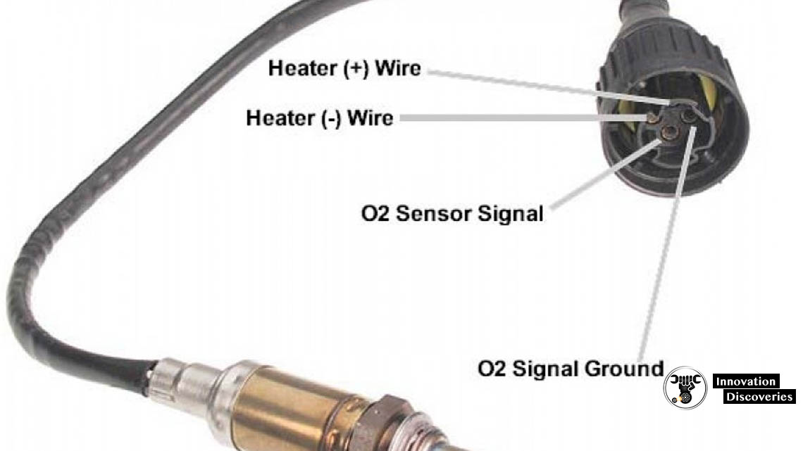
The probe typically has four wires attached to it:
1. two for the lambda output, and
2. two for the heater power,
although some automakers use the metal as a ground for the sensor element signal, resulting in three wires. Earlier non-electrically-heated sensors had one or two wires.
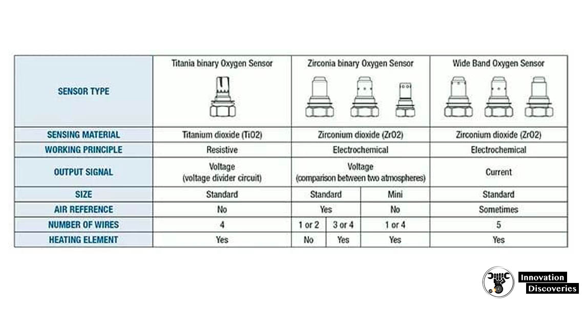
TYPES OF OXYGEN SENSORS
1. Zirconia sensor
The zirconium dioxide, or zirconia, lambda sensor is based on a solid-state electrochemical fuel cell called the Nernst cell. Its two electrodes provide an output voltage corresponding to the quantity of oxygen in the exhaust relative to that in the atmosphere.
An output voltage of 0.2 V (200 mV) DC represents a “lean mixture” of fuel and oxygen, where the amount of oxygen entering the cylinder is sufficient to fully oxidize the carbon monoxide (CO), produced in burning the air and fuel, into carbon dioxide (CO2). An output voltage of 0.8 V (800 mV) DC represents a “rich mixture”, which is high in unburned fuel and low in remaining oxygen. The ideal setpoint is approximately 0.45 V (450 mV) DC. This is where the quantities of air and fuel are in the optimal ratio, which is ~0.5% lean of the stoichiometric point, such that the exhaust output contains minimal carbon monoxide.
The voltage produced by the sensor is nonlinear with respect to oxygen concentration. The sensor is most sensitive near the stoichiometric point (where λ = 1) and less sensitive when either very lean or very rich.
The ECU is a control system that uses feedback from the sensor to adjust the fuel/air mixture. As in all control systems, the time constant of the sensor is important; the ability of the ECU to control the fuel–air ratio depends upon the response time of the sensor. Aging or fouled sensor tends to have a slower response time, which can degrade system performance. The shorter the time period, the higher the so-called “cross count” and the more responsive the system.
The sensor has a rugged stainless-steel construction internally and externally. Due to this the sensor has a high resistance to corrosion, allowing it to be used effectively in aggressive environments with high temperature/pressure.
The zirconia sensor is of the “narrow-band” type, referring to the narrow range of fuel/air ratios to which it responds.
2. Wideband zirconia sensor
A variation on the zirconia sensor, called the “wideband” sensor, was introduced by NTK in 1992 and has been widely used for car engine management systems in order to meet the ever-increasing demands for better fuel economy, lower emissions and better engine performance at the same time. It is based on a planar zirconia element, but also incorporates an electrochemical gas pump. An electronic circuit containing a feedback loop controls the gas-pump current to keep the output of the electrochemical cell constant so that the pump current directly indicates the oxygen content of the exhaust gas. This sensor eliminates the lean–rich cycling inherent in narrow-band sensors, allowing the control unit to adjust the fuel delivery and ignition timing of the engine much more rapidly. In the automotive industry, this sensor is also called a UEGO (universal exhaust-gas oxygen) sensor. UEGO sensors are also commonly used in aftermarket dyno tuning and high-performance driver air-fuel display equipment. The wideband zirconia sensor is used in stratified fuel injection systems and can now also be used in diesel engines to satisfy the upcoming EURO and ULEV emission limits.
Wideband sensors have three elements:
1. ion oxygen pump,
2. narrowband zirconia sensor,
3. heating element.
The wiring diagram for the wideband sensor typically has six wires:
1. resistive heating element,
2. resistive heating element,
3. sensor,
4. pump,
5. calibration resistor,
6. common.
3. Titania sensor
A less common type of narrow-band lambda sensor has a ceramic element made of Titania (titanium dioxide). This type does not generate its own voltage but changes its electrical resistance in response to the oxygen concentration. The resistance of the Titania is a function of the oxygen partial pressure and the temperature. Therefore, some sensors are used with a gas-temperature sensor to compensate for the resistance change due to temperature. The resistance value at any temperature is about 1/1000 the change in oxygen concentration. Luckily, at λ = 1, there is a large change of oxygen, so the resistance change is typically 1000 times between rich and lean, depending on the temperature.
As Titania is an N-type semiconductor with a structure TiO2−x, the x defects in the crystal lattice conduct the charge. So, for fuel-rich exhaust (lower oxygen concentration) the resistance is low, and for fuel-lean exhaust (higher oxygen concentration) the resistance is high. The control unit feeds the sensor with a small electric current and measures the resulting voltage drop across the sensor, which varies from nearly 0 volts to about 5 volts. Like the zirconia sensor, this type is nonlinear, such that it is sometimes simplistically described as a binary indicator, reading either “rich” or “lean”. Titania sensors are more expensive than zirconia sensors, but they also respond faster.
In automotive applications, the Titania sensor, unlike the zirconia sensor, does not require a reference sample of atmospheric air to operate properly. This makes the sensor assembly easier to design against water contamination. While most automotive sensors are submersible, zirconia-based sensors require a very small supply of reference air from the atmosphere. In theory, the sensor wire harness and connector are sealed. Air that leaches through the wire harness to the sensor is assumed to come from an open point in the harness – usually the ECU, which is housed in an enclosed space like the trunk or vehicle interior.


4 Comments