Anti-lock Braking System is a closed-loop control device that prevents wheel lock-up during braking and as a result vehicle stability and steering is maintained.
This system uses the principle of cadence braking and threshold braking.
The purpose of the Anti-lock Braking System (ABS) is to control the rate at which individual wheels accelerate and de-accelerate through the regulation of the line pressure applied to each foundation brake.
The control signals, generated by the controller and applied to the brake pressure modulating unit, are derived from the analysis of the outputs taken from wheel speed sensors.
Thus, when active, the Anti-lock Braking System (ABS) makes optimum use of the available friction between the tires and the road surface.
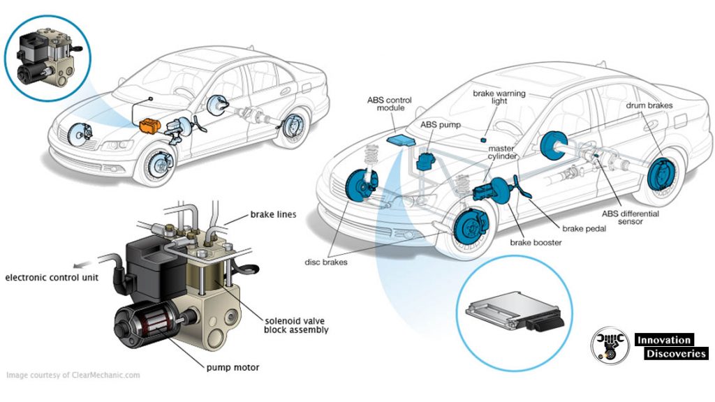
COMPONENTS OF ABS
There are four main components of the ABS:
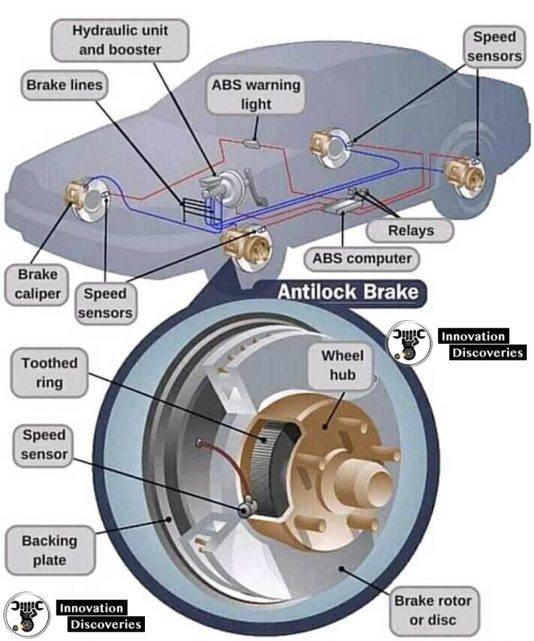
1. Speed sensor
The purpose of the speed sensor is to monitor the speed of each wheel and then to determine the acceleration and de-acceleration of the wheels.
It consists of the exciter(a ring with notched teeth)and a wire coil/magnet assembly which generates the pulses of electricity as teeth of exciter pass in front of it.
Read More About Sensors:
- VEHICLE SENSORS: FUNCTIONS AND TYPES
- 3 SYMPTOMS OF A FAULTY SPEED SENSOR IN YOUR VEHICLE
- 6 MOST COMMON CRANKSHAFT POSITION SENSOR SYMPTOMS
- RAIN SENSORS AND AUTOMATIC WIPERS: HOW DO THEY WORK?
- TYPES OF LIGHTING SENSORS
- WHAT IS PROXIMITY SENSOR, ITS TYPES AND WORKING
- HOW TO RESET TIRE PRESSURE SENSOR: A STEP-BY-STEP GUIDE
2. Valves
The function of the valves is to regulate the air pressure to brakes during the Anti-Lock Braking System (ABS) action.
They are placed in the brake line of each brake controlled by the ABS. In most cases, the valve has three positions:
- Position one, the valve is open and the pressure from the master cylinder is passed through the brake.
- In position two, the valve blocks the line resulting in isolating the brake from the master cylinder.
- While position three, the valve releases some of the pressure from brakes.
Read More:
- VALVE MECHANISM CONSTRUCTION
- VALVE SELECTION HANDBOOK | PDF
- A/C EXPANSION VALVE (HOW IT WORKS, FAILURE SYMPTOMS, AND REPLACEMENT COST)
3. Pump
The purpose of the pump is to regulate or restore the pressure back to the brakes that have been released by the valves.
4. Controller
The controller of the Anti-Lock Braking System (ABS) consists of the Electronic Control Unit(ECU) which processes all the ABS information and signal functions.
The ECU gets the information from all the wheels and then control or limit the brake force to each wheel.
Read More:
ECU CHIP TUNE | IGNITION TIMING | INCREASE HORSEPOWER
ABS BRAKE TYPES
Anti-lock braking system or ABS has different types of brakes based on the number of channels used.
1. Four-channel
This scheme is employed in most modern cars like Ferrari’s California T.
In this scheme, all four wheels have their speed sensors and valves.
This gives the best result as all the four wheels can be controlled Individually which ensures the maximum braking force.
2. Three-channel
Three-channel comes with two combinations, One is three-channel with four sensors and the Other one with three-channel and three sensors.
In a three-channel and four sensor scheme, along with the four sensors on each wheel, there is a separate valve for each of the front wheels and; A common valve for the rear wheels.
The three-channel and three sensor schemes are mostly employed in pickup trucks.
There are individual sensors and valves for both the front wheels with a common valve and sensor for both of the rear wheels.
3. Two-channel
This system works with four sensors and two valves.
It uses speed sensors at each wheel, With one control valve for both of the front wheels and the other one for the rear wheels.
4. One channel
This system is found on pickup trucks that use rear-wheel ABS.
It has one valve and one sensor for both of the rear wheels.
This system is not very effective because as there is a possibility that one of the rear wheels will lock, Reducing the effectiveness of brakes.
WORKING OF ABS
- When the brakes are applied, fluid is forced from the master cylinder to the HCU inlet ports with the help of open solenoid valves that are contained in the HCU, then through the outlet ports of HCU to each wheel.
- The rear part of the master cylinder feeds the front brakes and vice-versa.
- After the fluid is inserted in each wheel, the wheel starts locking-up.
- When the control module senses that the wheel is going to lock up, it closes the normally open solenoid valves for that wheel.
- The anti-lock brake control module then looks at anti-lock brake sensor signal from the affected wheel.
- Once the affected wheel comes back up to the speed,
- Then the control module returns the solenoid valve to there normal condition.
4 Comments