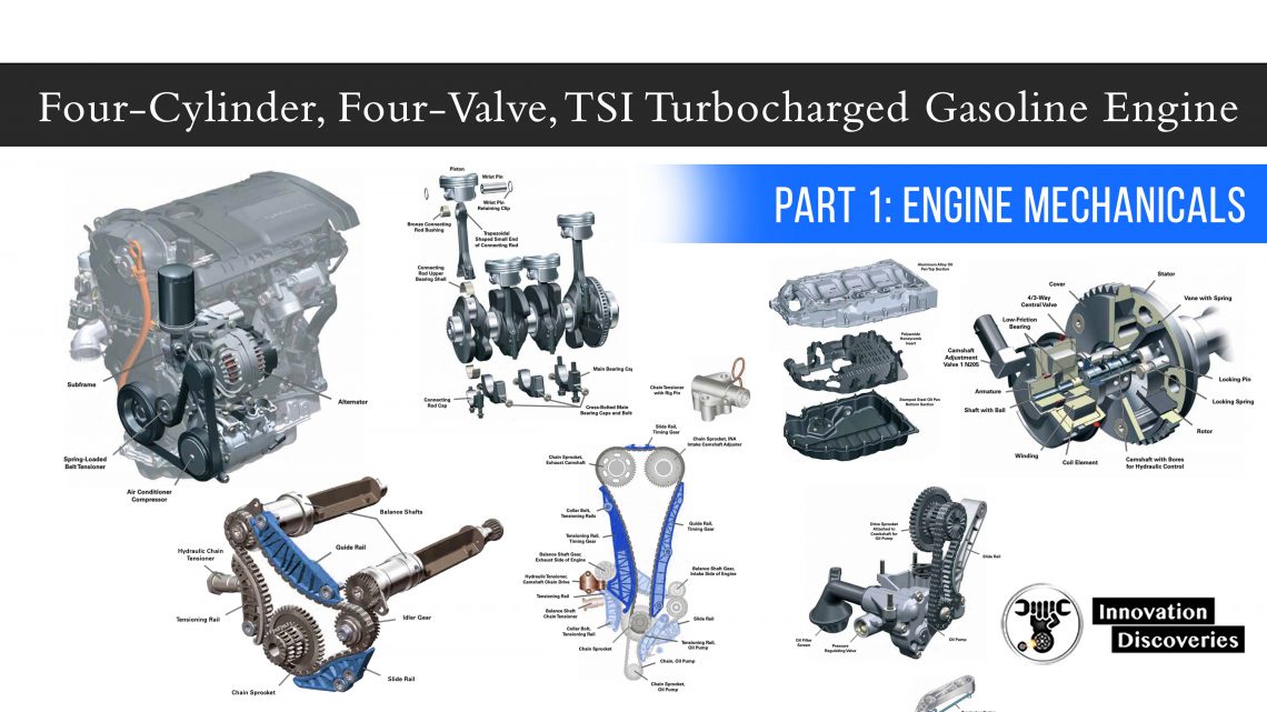
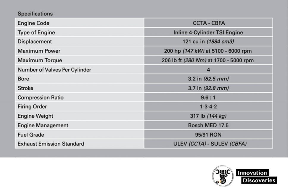
The Volkswagen 2.0 liter chain-driven TSI engine
PART 1: Engine Mechanicals
Engine Block
- Cast iron crankcase
- Balancer shafts in the crankcase
- Forged steel crankshaft
- sump-mounted oil pump—chain-driven by a crankshaft
- Timing gear chain — front end of engine
- Balancer—chain-driven at front end of engine
Cylinder Head
- 4-valve cylinder head
- 1 INA intake camshaft adjuster
Intake Manifold
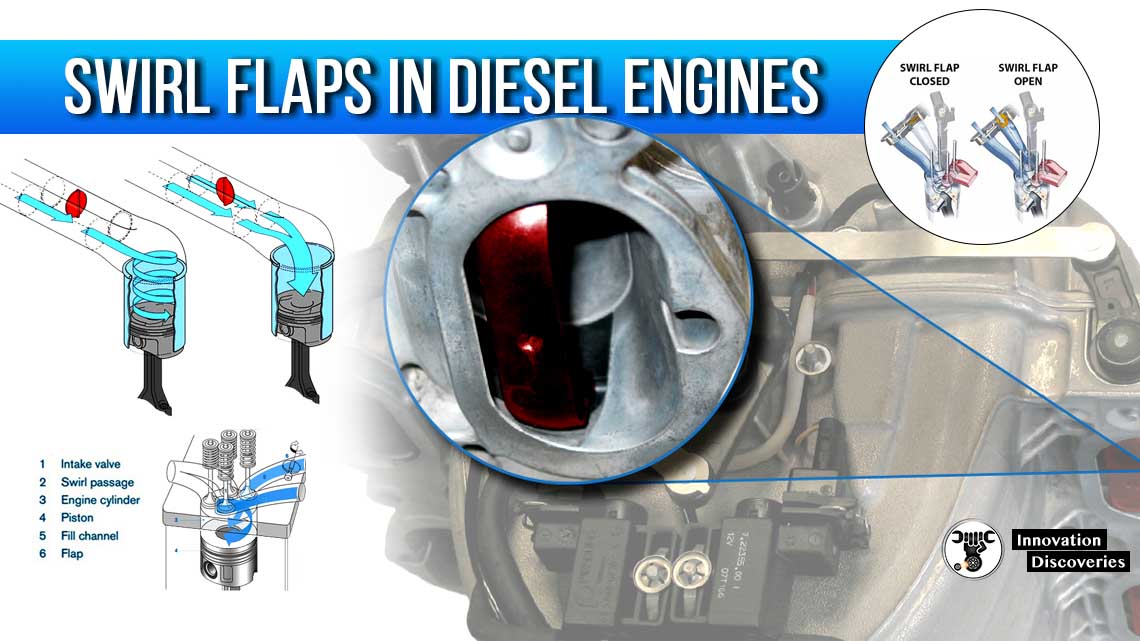
- Tumble flap
Fuel Supply
- Demand controlled on low and high-pressure ends.
- Multi-port high-pressure injector
Engine Management
- MED 17.5 engine control module
- Hot-film air mass flow with integral temperature sensor
- Throttle valve with contactless sensor
- Map-controlled ignition with cylinder-selective
- digital knock control
- Single-spark ignition coils
Turbocharging
- Integral exhaust turbocharger
- Charge-air cooler
- Boost pressure control with overpressure
- Electrical wastegate valve
Exhaust
- Single-chamber exhaust system with close
- coupled pre-catalyst
Combustion Process
- Fuel straight injection
Engine Mechanicals
Cylinder Block
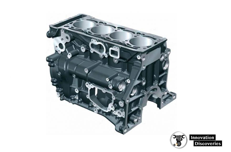
The cylinder block has a closed-deck configuration and is made of cast iron. It houses the five-bearing crankshaft assembly and the two balancer shafts.
The housing for mounting the chain drives is integrated in the block. The cylinder liners are finished in a three-stage fluid jet honing process.
The undersides of the pistons are cooled by engine oil supplied by spray jets mounted on the cylinder block.
The cylinder block is sealed on the transmission side by a sealing flange and gasket.
Oil Pan
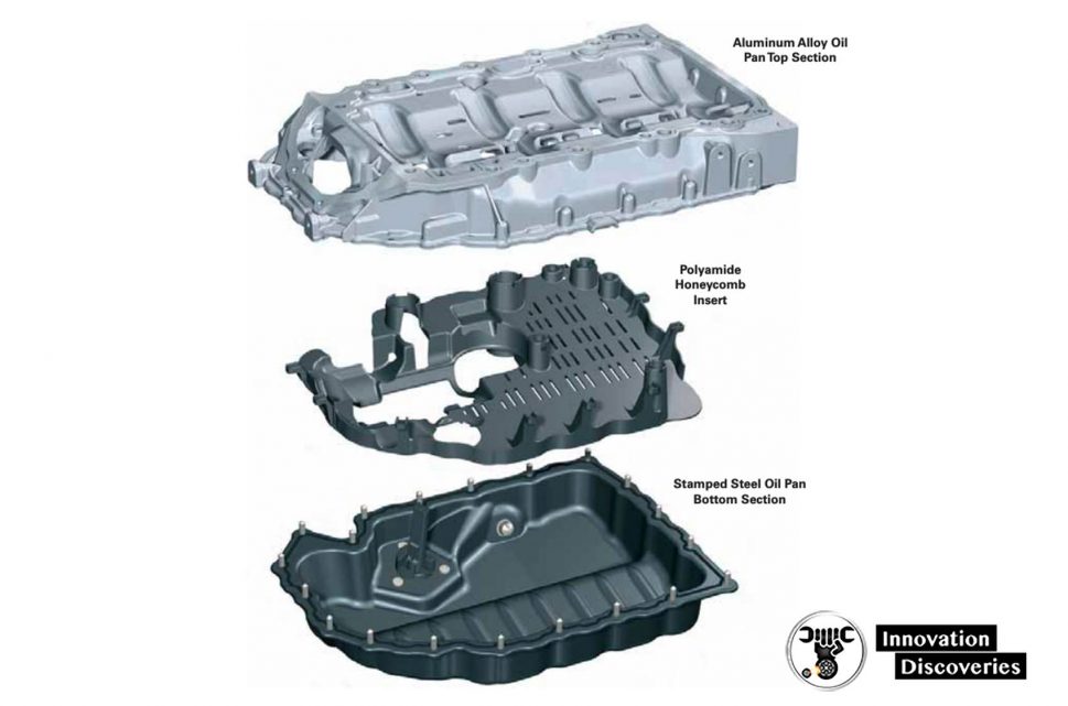
The oil pan consists of two sections.
The upper section is made of an aluminium alloy (AlSi12Cu) and reinforces the crankcase through a bedplate effect.
It also houses the oil pump. The upper section is bolted to the crankcase and sealed with a liquid sealant.
The bottom section is made of sheet steel (deep drawn, punched, and catalytically coated). It houses Oil Level Sensor G12 and the drain plug.
The bottom section is bolted to the upper section and sealed with a liquid sealant.
The oil pan has an integral honeycomb insert made of polyamide to prevent oil churning when the vehicle is driven aggressively.
Crankshaft
The five main bearing crankshaft is made of forged steel and induction hardened. Optimal balancing is achieved by using eight counterweights.
To additionally reinforce the crankshaft assembly, three inner main bearing caps are cross-bolted to the cylinder block.
Trapezoidal Connecting Rod (Small End)
- Material: 36MnVS4
- Length: 5.82 in (148 mm)
- Big-End Bearing: 1.88 in (47.8 mm)
- Small-End Bearing: 0.82 in (21 mm)
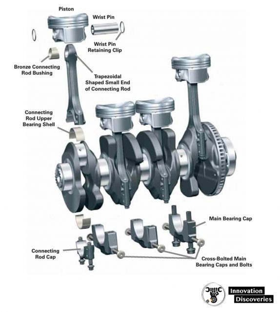
The crankshaft main bearings are a two-component type. Axial play of the crankshaft is controlled by thrust washers at the middle support bearing.
Bronze bushings are press-fit into the small trapezoidal upper end of the connecting rods.
The lower end of the connecting rods are cracked to ensure a precision fit and reduce movement of the bearing cap under load.
The upper and lower bearing shells of the connecting rod are not identical in composition.
The upper bearing shell is a two-component composite bearing while the lower shell is a three-component composite bearing.
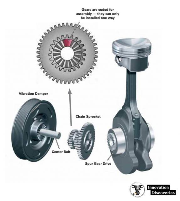
The chain drive sprocket is mounted to the crankshaft face and driven by a spur gear forged in the crankshaft.
The other end of the chain sprocket also has a spur gear surface which drives the vibration damper.
This method of joining allows high torque to be transmitted to the chain sprocket and vibration damper while keeping the diameter of the components small.
This allows better sealing by the radial shaft seal at the vibration damper hub.
Special tools are required during disassembly/assembly of these components to prevent damage to the gears.
On the transmission side of the engine, a dual mass flywheel or torque converter (depending on transmission) is mounted to the crankshaft with eight bolts.
Pistons
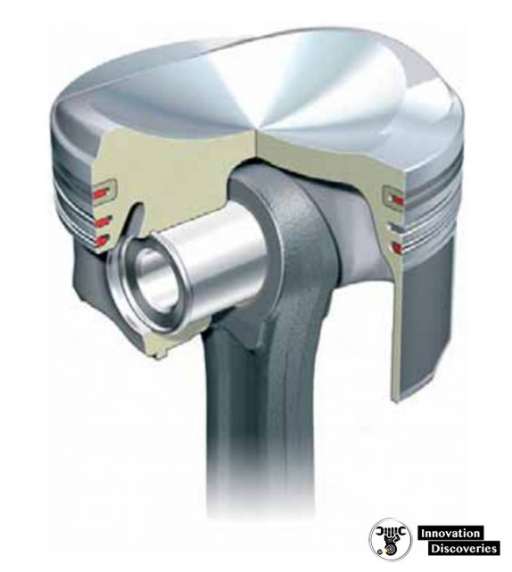
The pistons are specially designed for the TSI engine with a cast-in ring land for the upper piston ring.
Coated skirts are used to help reduce frictional losses.
The upper piston ring is rectangular, the second piston ring is a taper-faced ring, and the oil scraper ring is a beveled ring with expander.
The 31CrMoV wrist pins are held in place by snap rings. The bottom side of the pistons are cooled by engine oil from spray jets mounted on the cylinder block.
The 4-valve cylinder head is cast from aluminium alloy.
Intake and exhaust valves are actuated by roller cam followers supported by hydraulic valve lifters.
The intake and exhaust camshafts are chain-driven. The variable timing of the intake camshaft is accomplished through the INA camshaft adjustment system.
The cylinder head cover adds support by acting as a ladder frame and does not have to be disassembled to remove the cylinder head.
The diagonal opening and sealing face simplifies drive chain installation.
Features
- Crossflow cylinder head made of ASi10Mg
- Three-layer metal head gasket
- Intake ports divided by baffle plate
- Cylinder head cover is made of AlSi9Cu3 with an integrated ladder frame bolted to the cylinder head and sealed with liquid sealant.
- Intake valve: solid-stem valve, chrome-plated with reinforced seat
- Exhaust valve: sodium-filled hollow-stem valve, chrome-plated and tempered with reinforced seat
- Single valve spring made of steel
- Roller cam followers running in needle bearings, hydraulic valve clearance adjustment.
- Hydro-formed assembled intake camshaft with variable valve timing, dwell angle of 190°, valve lift of 10.7 mm
- Hydro-formed assembled exhaust camshaft with press-fit drive gear, dwell angle of 180°, valve lift of 8 mm.
- INA Camshaft Adjuster, timing range of 60° crank angle, the basic position is locked in “retard” (engine not running).
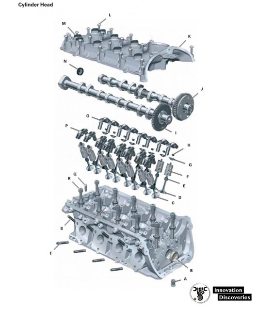
- A: Check valve
- B: Sealing end cap
- C: Exhaust valve
- D: Intake valve
- E: Valve stem seal
- F: Valve spring
- G: Valve spring retainer
- H: Valve keeper
- I: Exhaust camshaft
- J: Intake camshaft with INA adjuster
- K: Cylinder head cover
- L: Cylinder head cover screw
- M: Screw plug
- N: Sealing end cap
- O: Hydraulic valve clearance adjuster
- P: Roller cam follower
- Q: Dowel pin
- R: Cylinder head bolt with washer
- S: Exhaust manifold locating pin
- T: Exhaust manifold stud
Bearing Bridge
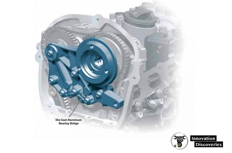
A die-cast aluminium bearing bridge mounted at the front of the cylinder head has the following tasks:
- Supporting the camshafts
- Supplying pressurized oil to camshaft bearings
- Supplying pressurized oil to the camshaft adjuster
- Controlling the axial movement of camshafts
- Mounting point for Camshaft Adjustment Valve 1 N205
The bearing bridge also serves to connect the two oil galleries of the cylinder head.
A check valve and filter screen are integrated in the pressurized oil duct to the INA camshaft adjuster.
INA Camshaft Adjustment System
The 2.0L TSI engine uses a hydraulic vane cell adjuster on the intake camshaft to affect valve timing.
Only the intake camshaft has variably adjusted timing on this engine. Oil pressure for this task is provided by the engine oil pump.
The variable camshaft adjuster provides an adjustment range of 60° crank angle. The camshaft is locked in the retard position at engine shut-off.
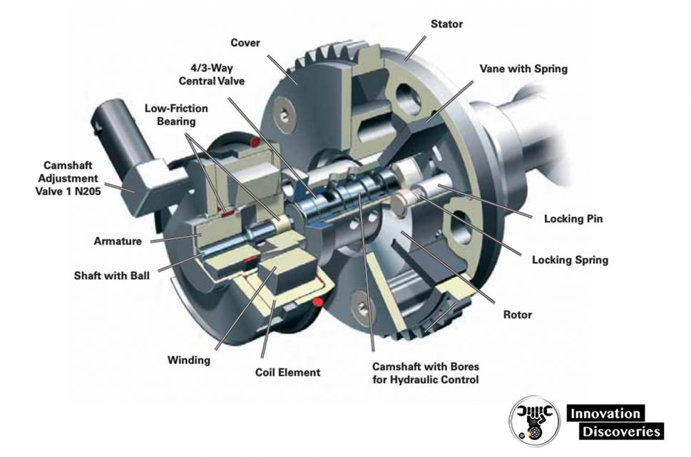
This function is performed by a spring-loaded locking pin. The camshaft is released when the engine oil pressure exceeds 7.25 psi (0.5 bar).
The rotor of the vane cell adjuster is welded to the intake camshaft. The 4/3-way central valve required for adjuster control is integrated in the camshaft.
Intake camshaft timing is map-controlled by the engine control module.
The goals are to improve engine power, enhance running smoothness, and reduce emissions (through internal exhaust gas recirculation).
Function
Pressurized oil flows to the central valve via the camshaft bearing through bores in the camshaft.
From here, depending on adjustment requirements, the oil flows through additional bores in the camshaft to one of the chambers in the adjuster.
Valve Timing
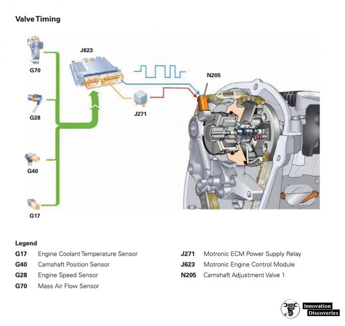
The valve is activated electrically via Camshaft Adjustment Valve 1 N205. When activated by a PWM signal, the solenoid produces a variable magnetic field.
Depending on the strength of the magnetic field, the shaft with ball is shifted towards the camshaft axis of rotation.
This, in turn, displaces the 4/3-way central valve and allows the oil to flow to the corresponding chamber.
The new design has many advantages.
It provides a very high adjustment rate capability even in unfavourable conditions such as cold starts or high oil temperatures during engine idling.
Chain Drive
All three chains of the 2.0L engine are driven directly by the chain sprocket mounted to the crankshaft.
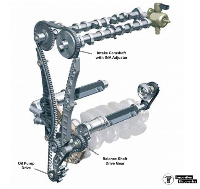
The chains are arranged in three planes (levels).
- 1st Plane – Balance Shaft Drive
- 2nd Plane – Camshaft Drive
- 3rd Plane – Oil Pump Drive
Gear chains (as opposed to roller chains) are used in all three planes. They are 1/4 inch gear chains whose tension is controlled by four tension plates and five guide plates.
Gear chains are more wear-resistant and produce less noise than roller chains.
The amount of space required for a given power transmission capacity is less than that of a timing belt or roller chain.
Gear chains are highly flexible in application because their width can be adapted for any power requirement by selecting the number of plates accordingly.
They have an efficiency of approximately 99%.
1st Plane — Balance Shaft Drive
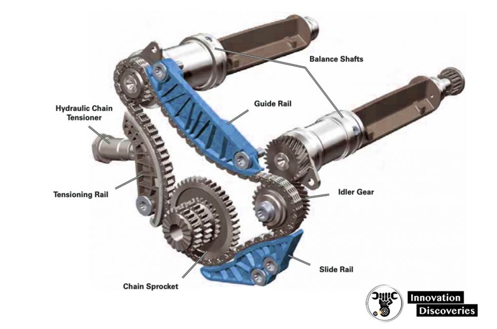
Two-cylinder block housed balance shafts are used to counteract unwanted vibration at engine speeds above 4000 rpm from being transmitted to the car body.
The balance shafts run at twice the engine speed in opposite directions from one another.
The direction of the second shaft is reversed by an idler gear.
The horizontally staggered arrangement of the balance shafts also helps reduce vibration.
The balance shafts are made from spheroidal graphite cast iron and run in three bearings.
Chain lubrication is provided by oil returning from the cylinder head. Oil is collected and distributed to the chain by a separate lubrication channel.
Mounting the balance shafts in the cylinder block has the following advantages:
- The cylinder block provides higher rigidity
- Oil foaming is eliminated by moving the rotating parts away from the oil sump
Balance Shaft Layout
The oil return channel from the cylinder head is located on the exhaust side of the cylinder block.
Return oil flows through the balance shaft housing. The balance shaft is mounted in a plastic pipe.
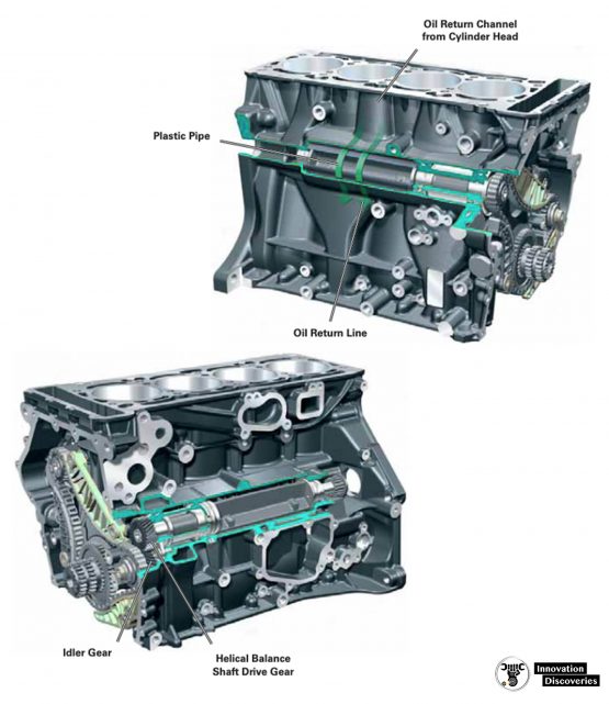
This prevents oil returning from the cylinder head from churning and foaming from direct contact with the balance shaft.
2nd Plane — Camshaft Drive
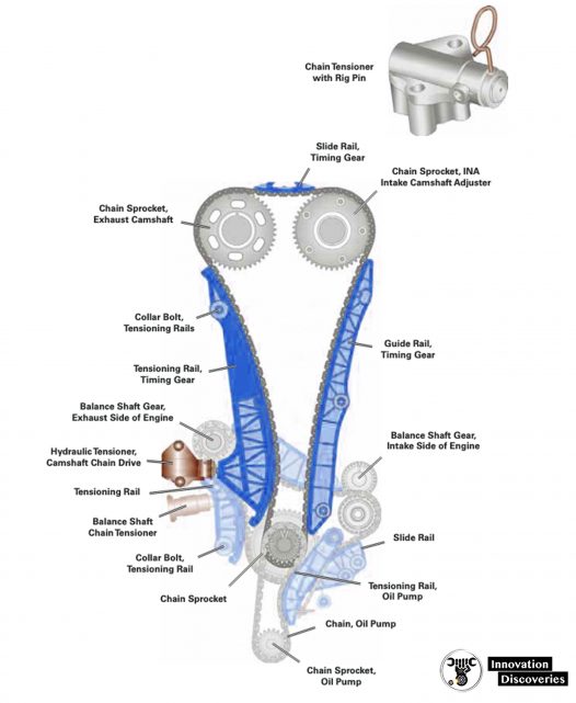
The camshafts are driven by a chain positioned on the second level. Tensioning is accomplished by a hydraulic tensioner.
The tensioner can be accessed through a service opening.
This allows the timing chain to be detached after removing the cylinder head without having to remove the engine timing cover.
3rd Plane — Oil Pump Drive
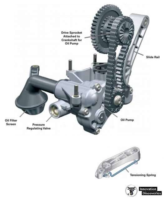
The chain drive for the oil pump is located in the third plane. A polyamide slide rail is used in this drive to locate and tension the chain.
The tension is produced by a mechanical spring.
A hydraulically damped system is not needed due to the low dynamic load.
The chain is lubricated by return oil or by the oil in the oil pan.
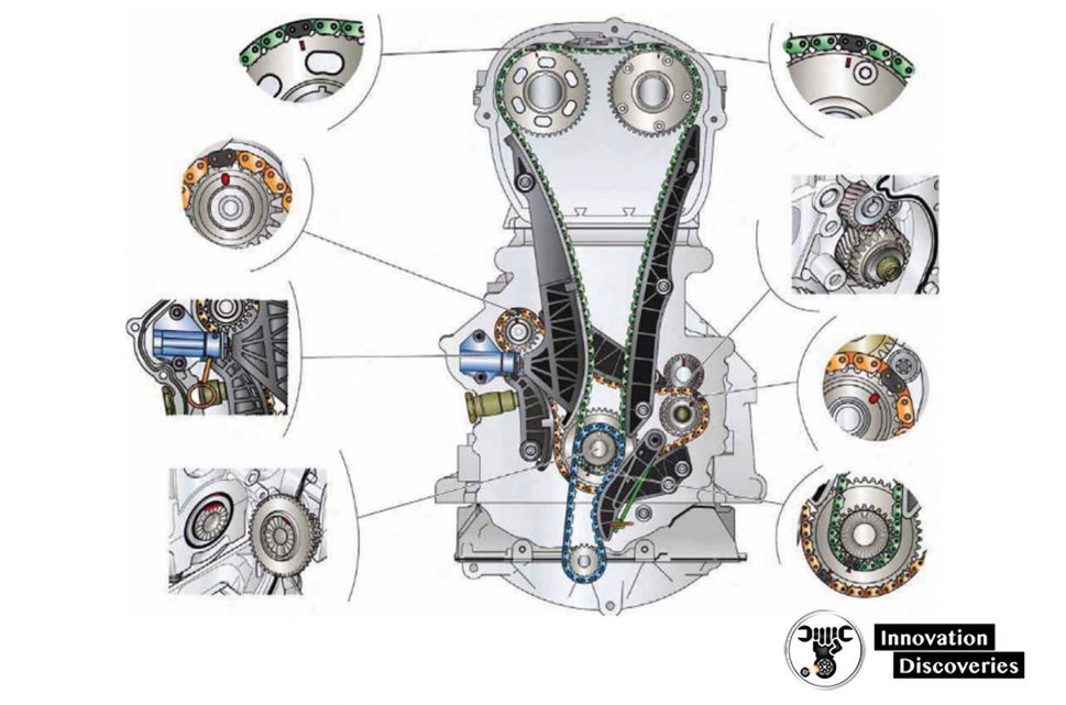
Each drive chain has a special dark link. The dark links are only on one side of the drive chain facing out from the engine block.
For the adjustment of the camshaft drive, the markings on the chain sprockets must align with the dark links of the chain.
However, to bring the camshaft drive gears into alignment with TDC by rotating the crankshaft requires approximately 166 revolutions of the crankshaft.
Therefore, during repairs when the drive chains must be removed, it is acceptable that the technician uses the dark links as a guide and make his markings on the sprockets.
Alternator/AC Compressor Drive
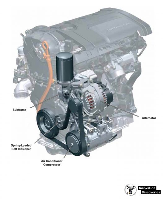
A subframe supports both the alternator and air conditioning compressor.
They are driven by a poly-vee belt which is tensioned by a spring-loaded tensioner.
©Volkswagen Group of America, Inc.
NEXT PART: Lubrication System
Stay Tune…
Discover More:
Visit Forum
Visit Our Friendly Website


