Refining Operations
Petroleum refining processes and operations can be separated into five basic areas:
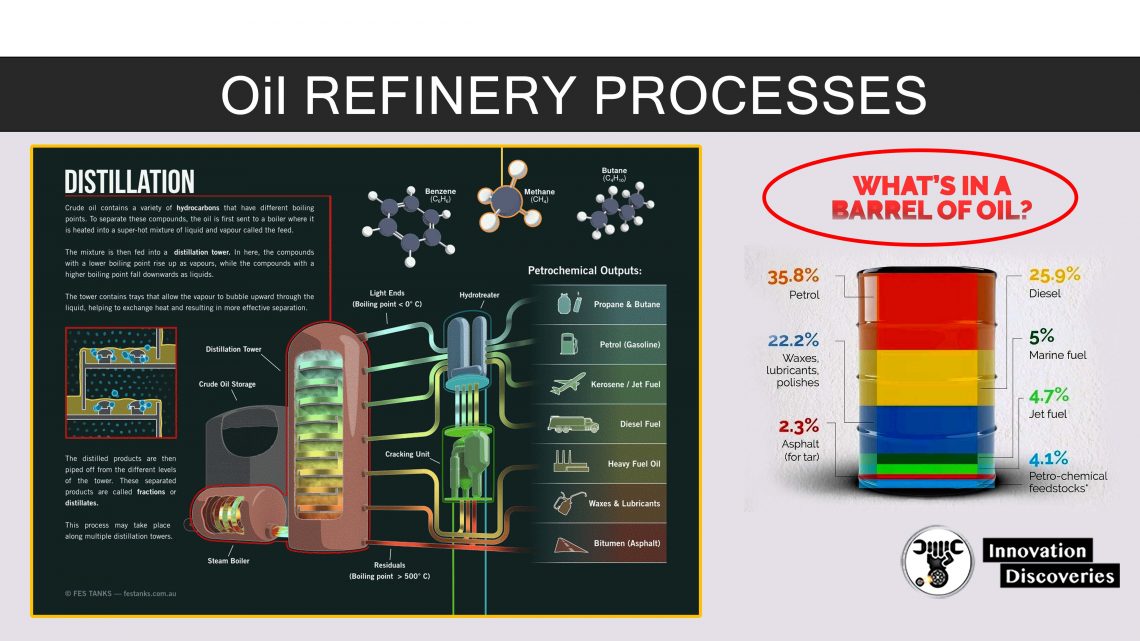
Fractionation (distillation) is the separation of crude oil in atmospheric and vacuum distillation towers into groups of hydrocarbon compounds of differing boiling-point ranges called “fractions” or “cuts.”
Conversion Processes change the size and/or structure of hydrocarbon molecules. These processes include: :
- Decomposition (dividing) by thermal and catalytic cracking;
- Unification (combining) through alkylation and polymerization; and
- Alteration (rearranging) with isomerization and catalytic reforming.
Treatment Processes to prepare hydrocarbon streams for additional processing and to prepare finished products. Treatment may include removal or separation of aromatics and naphthenes, impurities and undesirable contaminants.
Treatment may involve chemical or physical separation e.g. dissolving, absorption, or precipitation using a variety and combination of processes including desalting, drying, hydrodesulfurizing, solvent refining, sweetening, solvent extraction, and solvent dewaxing.
Formulating and Blending is the process of mixing and combining hydrocarbon fractions, additives, and other components to produce finished products with specific performance properties.
Other Refining Operations include:
- Light-ends recovery;
- Sour-water stripping;
- Solid waste, process-water and wastewater treatment;
- Cooling, storage and handling and product movement;
- hydrogen production;
- Acid and tail-gas treatment;
- and sulfur recovery.
Modern Petroleum Processing
Seven Basic Operations in Petroleum Processing
Separation
- Distillation
- Solvent refining
Conversion
- Carbon removal
- Hydrogen addition
Reforming
- Catalytic reforming
- Steam/Hydrocarbon reforming
Rearrangement
- Isomerization
Combination
- Catalytic polymerization
- Alkylation
Treating, Finishing, Blending
- Gasoline, kerosene and diesel
- Lubes and waxes
- Asphalt
Protecting the Environment
- Wastewater treatment
- Disposal of solids
- Sulfur recovery
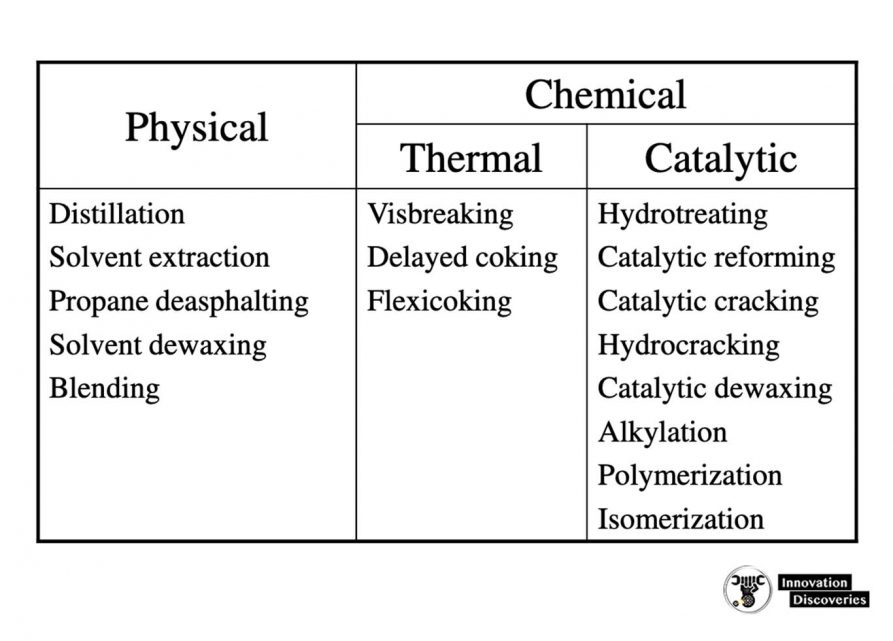
Physical and chemical processes
A typical layout for an oil refinery
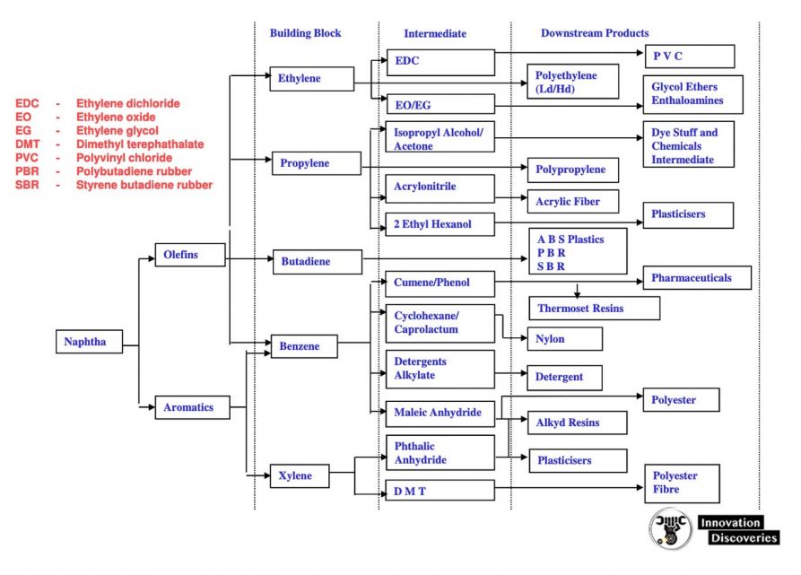
PETROCHEMICAL PRODUCT TREE
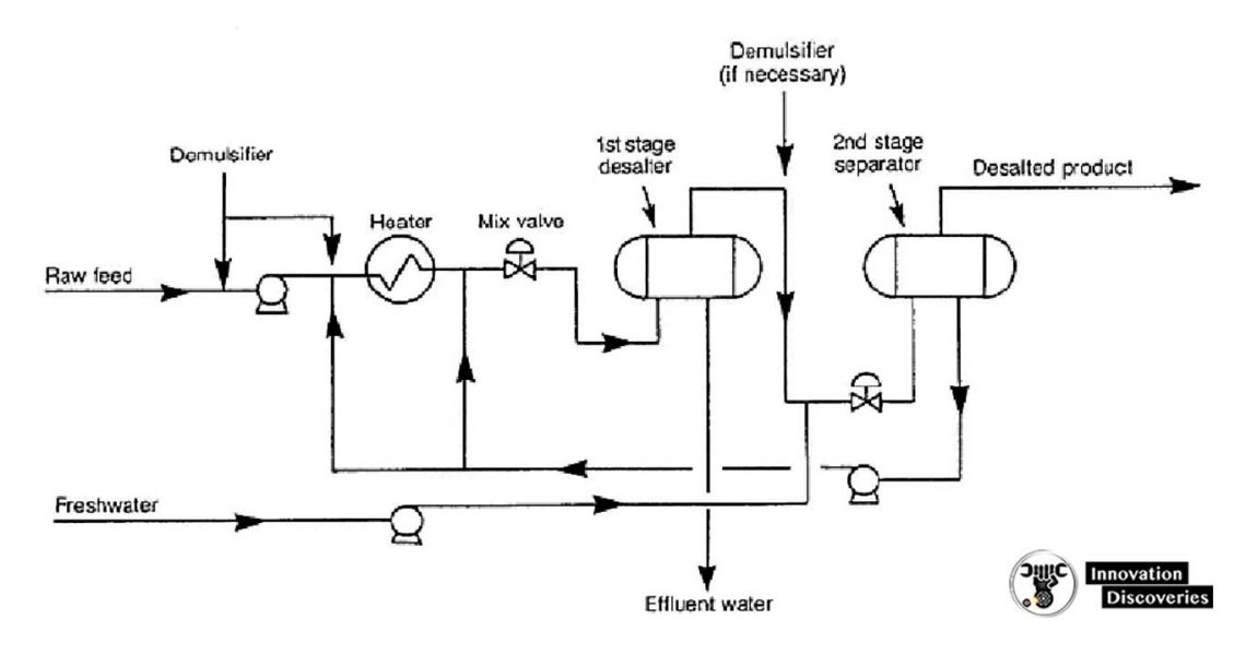
DESALTING
- Crude oil distillation is more complicated than product distillation, in part because crude oils contain water, salts, and suspended solids.
- Step 1 in the refining process is to remove these contaminants to reduce corrosion, plugging, and fouling of equipment and to prevent poisoning catalysts in processing units.
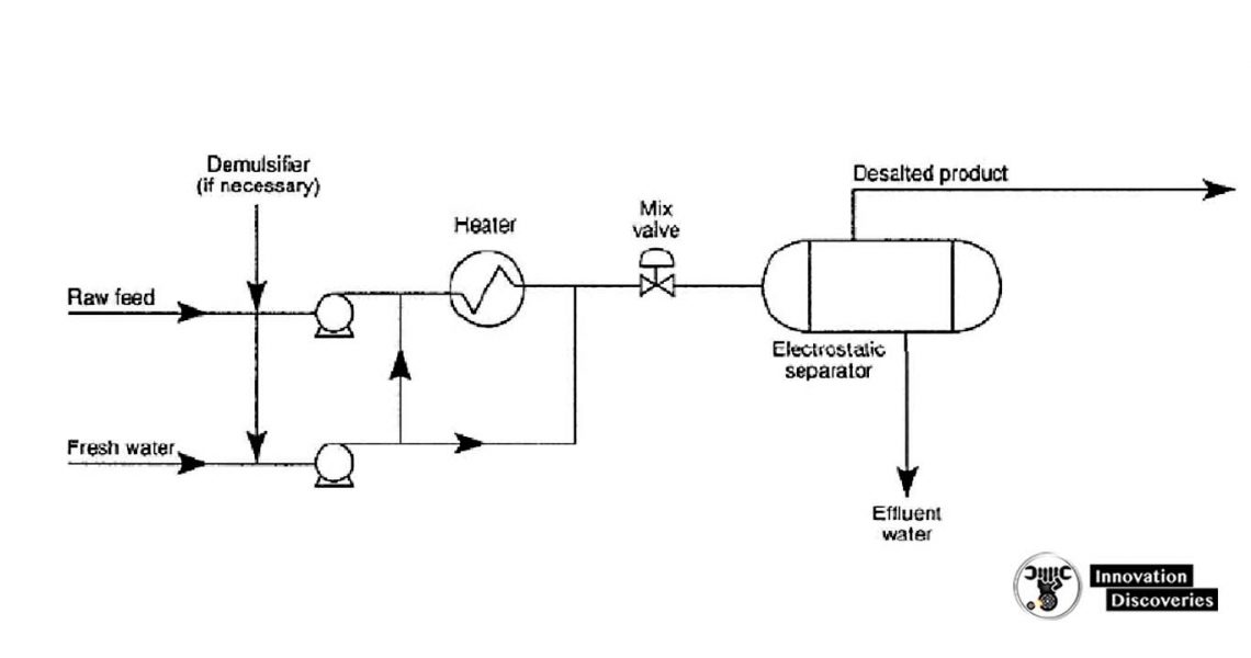
- Step 2 most typical methods of crude-oil desalting are chemical and electrostatic separation, and both use hot water as the extraction agent.
- In chemical desalting, water and chemical surfactant (demulsifiers) are added to the crude, which is heated so that salts and other are added to the crude, which is heated so that salts and other impurities dissolve or attach to the water, then held in a tank to settle out.
- Electrical desalting is the application of high-voltage electrostatic charges to concentrate suspended water globules in the bottom of the settling tank. Surfactants are added only when the crude has a large number of suspended solids.
- Step 3(and rare) process filters hot crude using diatomaceous earth.
- The salts are dissolved in the wash water and the oil and water phases are separated in a settling vessel either by adding chemicals to assist in breaking the emulsion or by developing a high-potential electrical field across the settling vessel to coalesce the droplets of salty water more rapidly.
- Either AC or DC fields may be used and potentials from 12,000 to 35,000 volts are used to promote coalescence.
- For single-stage desalting units, 90 to 95% efficiencies are obtained and two-stage processes achieve 99% or better efficiency.
- If the pH of the brine exceeds 7, emulsions can be formed because of the sodium naphthenate and sodium sulfide Present.
- For most crude oils it is desirable to keep the pH below 8.0. Better dehydration is obtained in electrical desalters when they are operated in the pH range of 6 to 8 with the best dehydration obtained at a pH near 6.
- The pH value is controlled by using another water source or by the addition of acid to the inlet or recycled water.
- The crude oil feedstock is heated to 65-180°C to reduce viscosity and surface tension for easier mixing and separation of the water.
- The temperature is limited by the vapour pressure of the crude-oil feedstock.
- In both methods, other chemicals may be added. Ammonia is often used to reduce corrosion. Caustic or acid may be added to adjust the pH of the water wash.
- Wastewater and contaminants are discharged from the bottom of the settling tank to the wastewater treatment facility.
Single-stage electrostatic desalting systems
Two-stage electrostatic desalting systems
Desalting / Dehydration
Industrial process furnaces
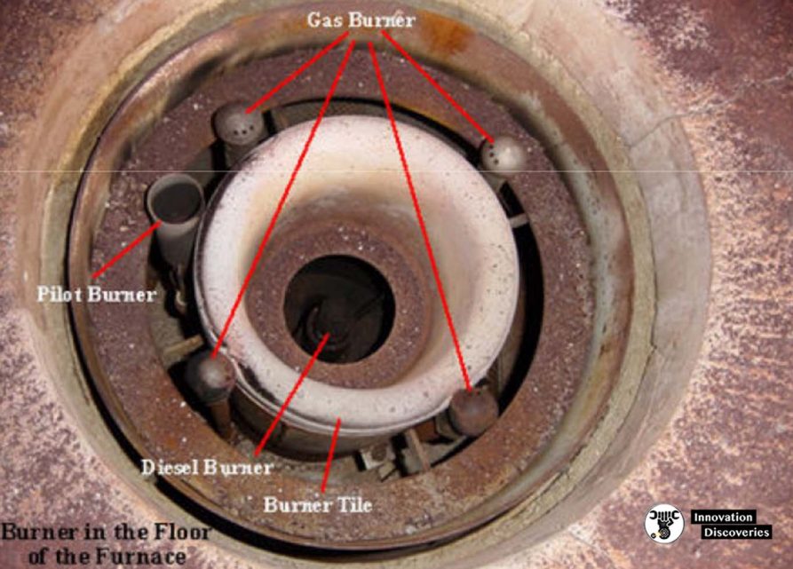
- Fuel flows into the burner and is burnt with air provided by an air blower. There can be more than one burner in a particular furnace which can be arranged in cells which heat a particular set of tubes.
- Burners can also be floor-mounted, wall-mounted or roof mounted depending on the design.
- The flames heat up the tubes, which in turn heat the fluid inside the first part of the furnace known as the radiant section or firebox.
- The heating fluid passes through the tubes and is thus heated to the desired temperature.
- The gases from the combustion are known as flue gas. After the flue gas leaves the firebox, most furnace designs include a convection section where more heat is recovered before venting to the atmosphere through the flue gas stack. (HTF=Heat Transfer Fluid.
- This heated fluid is then circulated to the whole plant to heat exchangers to be used wherever heat is needed instead of directly heating the product line as the product or material may be volatile or prone to cracking at the furnace temperature.)
Schematic diagram of an Industrial Process Furnace
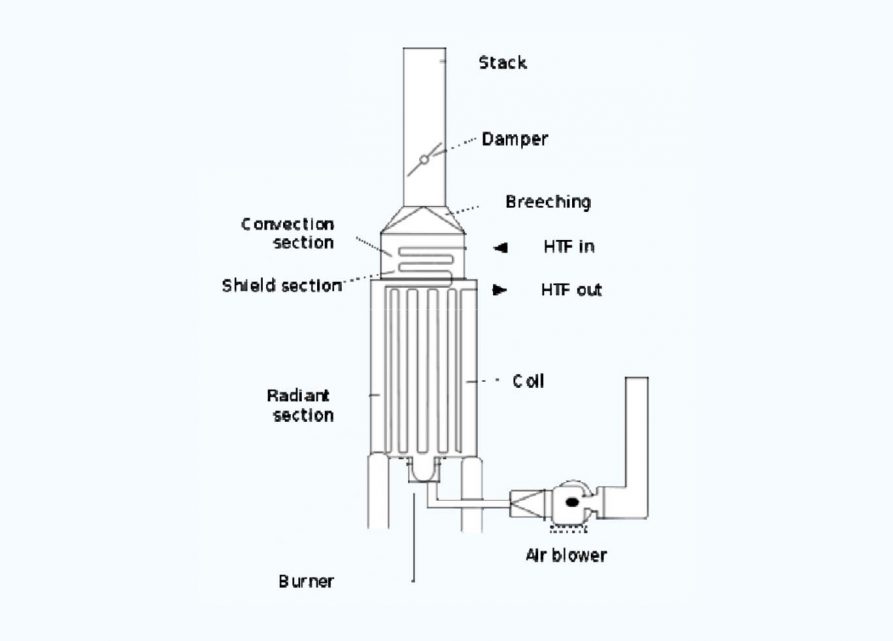
1. Radiant section
2. Convection section
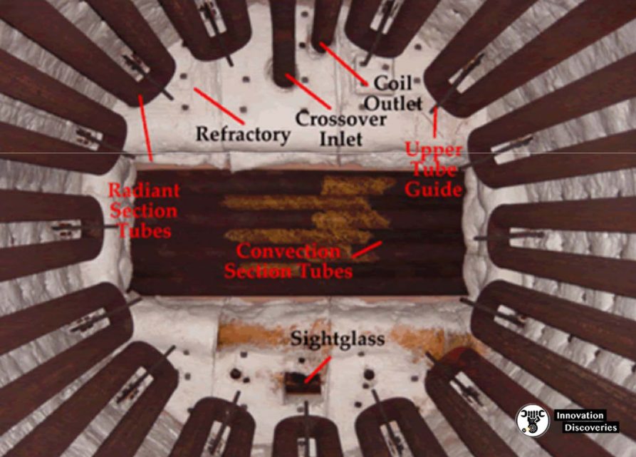
- The convection section is located above the radiant section where it is cooler to recover additional heat.
- Heat transfer takes place by convection here, and the tubes are finned to increase heat transfer.
- The first two tube rows at the bottom of the convection section and the top of the radiant section are an area of bare tubes (without fins) because they are still exposed to plenty of radiation from the firebox.
- Crossover is the term used to describe the tube that connects from the convection section outlet to the radiant section inlet.
- The sight glass at the top allows personnel to see the flame shape and pattern from above and visually inspect if flame impingement is occurring.
- Flame impingement happens when the flame touches the tubes and causes small isolated spots of very high temperature.
3. Burner
4. Soot blowers
- Soot blowers are found in the convection section.
- As this section is above the radiant section and air movement is slower because of the fins, soot tends to accumulate here.
- Soot blowing is normally done when the efficiency of the convection section is decreased.
- Soot blowers utilize flowing media such as water, air or steam to remove deposits from the tubes. This is typically done during maintenance with the air blower turned on.
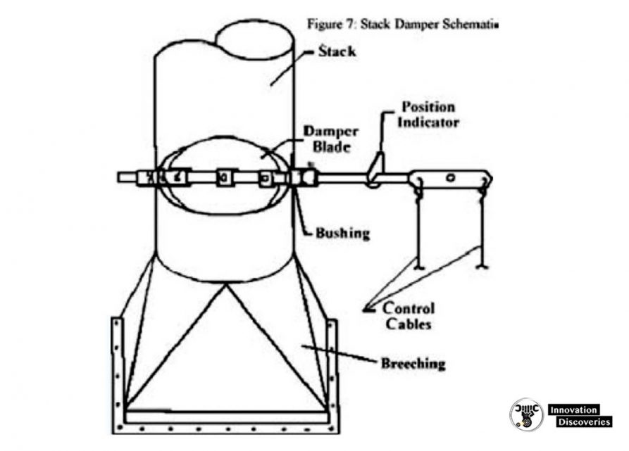
5. Stack
- As the damper closes, the amount of heat escaping the furnace through the stack decreases, but the pressure or draft in the furnace increases which poses risks to those working around it.
- if there are air leakages in the furnace the flames can then escape out of the firebox or even explode if the pressure is too great.
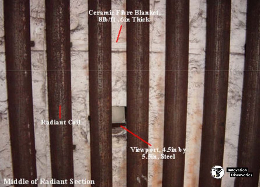
6. Insulation
- Insulation is an important part of the furnace because it prevents excessive heat loss.
- Refractory materials such as firebrick, castable refractories and ceramic fibre, are used for insulation.
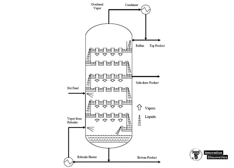
DISTILLATION
- Distillation is based on the fact that the vapour of a boiling mixture will be richer in the components that have lower boiling points.
- Thus, when this vapour is cooled and condensed, the condensate will contain the more volatile components. At the same time, the original mixture will contain more of the less volatile components.
- Fractional distillation is useful for separating a mixture of substances with narrow differences in boiling points and is the most important step in the refining process.
- Distillation can contribute to more than 50% of plant operating costs.
- Very few of the components come out of the fractional distillation column ready for market.
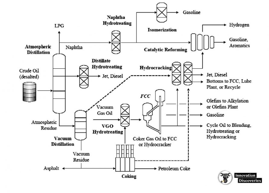
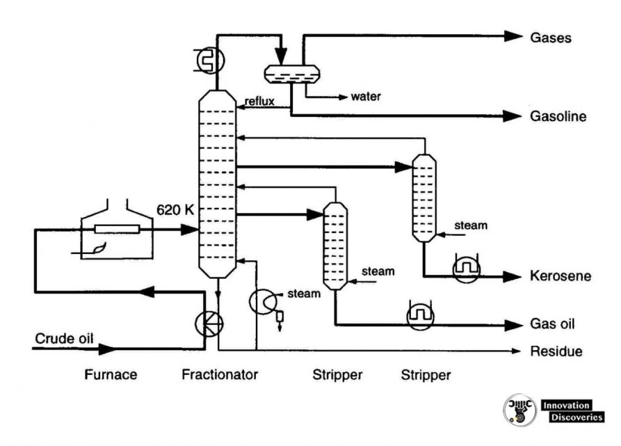
1. Atmospheric distillation
- The refining process is the separation of crude oil into various fractions or straight-run cuts by distillation in atmospheric and vacuum towers.
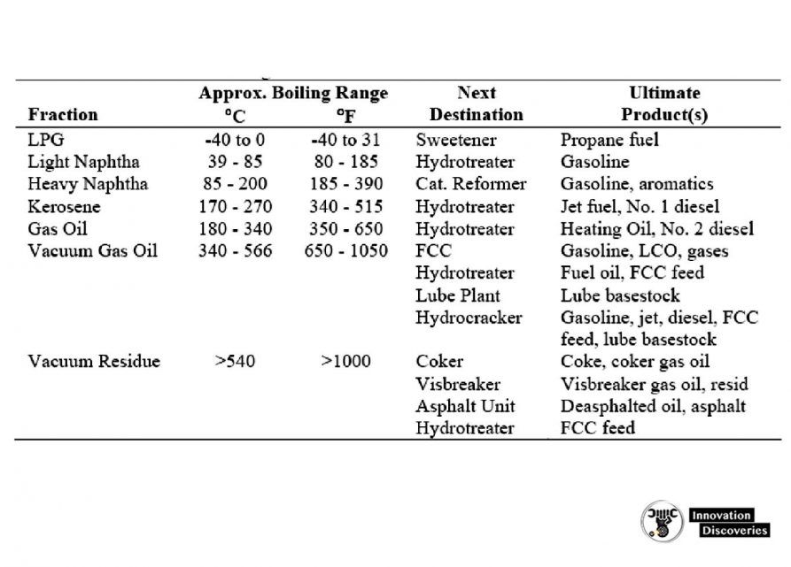
- The main fractions or “cuts” obtained have specific boiling-point ranges and can be classified in order of decreasing volatility into gases, light distillates, middle distillates, gas oils, and residuum.
- The desalted crude feedstock is preheated using recovered process heat.
- The feedstock then flows to a direct-fired crude charge heater and then into the vertical distillation column just above the bottom, at pressures slightly above atmospheric and at temperatures ranging from 340-370°C (above these temperatures undesirable thermal cracking may occur). All but the heaviest fractions flash into vapour.
- As the hot vapour rises in the tower, its temperature is reduced.
- Heavy fuel oil or asphalt residue is taken from the bottom.
- At successively higher points on the tower, the various major products including lubricating oil, heating oil, kerosene, gasoline, and uncondensed gases (which condense at lower temperatures) are drawn off.
- The temperature of crude oil is raised to about 288°C by heat exchange with product and reflux streams.
- It is then further heated to about 399°C in a furnace and charged to the flash zone of the atmospheric fractionators.
- The furnace discharge temperature is sufficiently high 343 to 399°C to cause vaporization of all products withdrawn above the flash zone plus about 10 to 20% of the bottoms product.
Reflux is provided by
- Condensing the tower overhead vapours and returning a portion of the liquid to the top of the tower.
- Pump-around and pump-back streams lower in the tower.
- Each of the side stream products removed from the tower decreases the amount of reflux below the point of draw-off.
- Maximum reflux and fractionation are obtained by removing all heat at the top of the tower, but this results in an inverted cone-type liquid loading which requires a very large diameter at the top of the tower.
- To reduce the top diameter of the tower and even the liquid loading over the length of the tower, intermediate heat-removal streams are used to generate reflux below the sidestream removal points.
- To accomplish this, the liquid is removed from the tower, cooled by a heat exchanger, and returned to the tower or a portion of the cooled sidestream may be returned to the tower.
- This cold stream condenses more of the vapours coming up the lower and thereby increases the reflux below that point.
- Although crude towers do not normally use reboilers, several trays generally incorporated below the flash zone and steam is are generally incorporated below the flash zone and steam is introduced below the bottom tray to strip any remaining gas oil from the liquid in the flash zone and to produce a high-flash-point bottom.
- The atmospheric fractionator normally contains 30 to 50 fractionation trays.
- Separation of the complex mixtures in crude oils is relatively easy and generally, five to eight trays are needed for each sidestream product plus the same number above and below the feed plate.
- Thus, a crude oil atmospheric fractionation tower with four liquid sidestream draw-offs will require from 30 to 42 trays.
- The liquid sidestream withdrawn from the tower will contain low-boiling components which lower the flashpoint. These ‘light ends’’ are stripped from each sidestream in a separate small stripping tower containing four to ten trays with steam introduced under the bottom tray.
- The steam and stripped light ends are vented back into the vapour zone of the atmospheric fractionator above the corresponding side-draw tray.
- The overhead condenser on the atmospheric tower condenses the pentane and- a heavier fraction of the vapours that passes out of the top of the tower.
- This is the light gasoline portion of the overhead, containing some propane and butanes and essentially all of the higher-boiling components in the tower overhead vapour.
- Some of this condensate is returned to the top of the tower as reflux, and the remainder is sent to the stabilization section of the refinery gas plant where the butanes and propane are separated from the C5-180°F (C5-82°C) LSR gasoline.
Simple crude distillation
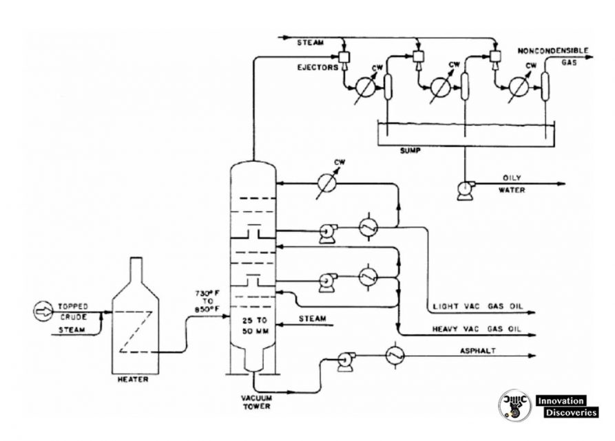
2. Vacuum distillation
- The furnace outlet temperatures required for atmospheric pressure distillation of the heavier fractions of crude oil are so high that thermal cracking would occur, with the resultant loss of product and equipment fouling.
- The process takes place in one or more vacuum distillation towers.
- The principles of vacuum distillation resemble those of fractional distillation except that larger diameter columns are used to maintain comparable vapour velocities at reduced pressures.
- The internal designs of some vacuum towers are different from atmospheric towers in that random packing is used instead of trays.
- A typical first-phase vacuum tower may produce gas oils, lubricating-oil base stocks, and heavy residual for propane deasphalting.
- A second-phase tower operating at a lower vacuum may distil surplus residuum from the atmospheric tower, which is not used for lube stock processing, and surplus residuum from the first vacuum tower not used for deasphalting.
- Vacuum towers are typically used to separate catalytic cracking feedstock from surplus residuum.
- Distillation is carried out with absolute pressures in the tower flash zone area of 25 to 40 mmHg.
- The addition of steam to the furnace inlet increases the furnace tube velocity and minimizes coke formation in the furnace as well as decreasing the total hydrocarbon partial pressure in the vacuum tower.
- Furnace outlet temperatures are also a function of the boiling range of the feed and the fraction vaporized as well as of the feed coking characteristics.
- Furnace outlet temperatures in the range of 388 to 454°C are generally used The lower operating pressures cause significant increases in the volume of vapour per barrel vaporized and, as a result, the vacuum distillation columns are much larger in diameter than atmospheric towers. It is not unusual to have vacuum towers up to 40 feet in diameter.
Modern Crude Distillation
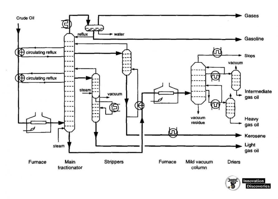
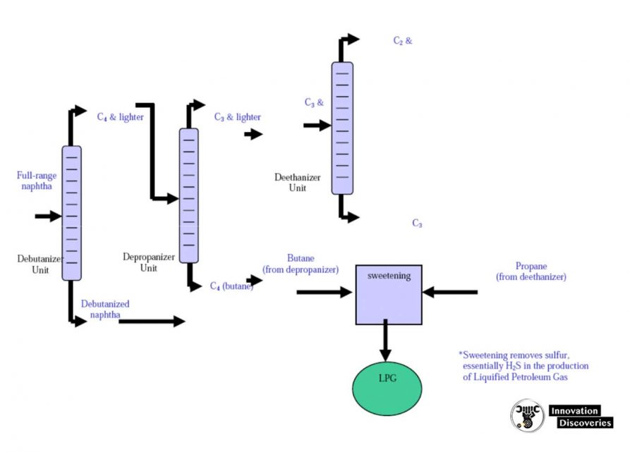
3. Light End Fractionation
- Within refineries there are numerous other, smaller distillation towers called columns, designed to separate specific and unique products.
- Columns all work on the same principles as the towers described above.
- For example, a depolarizer is a small column designed to separate propane and lighter gases from butane and heavier components in the light-end unit.
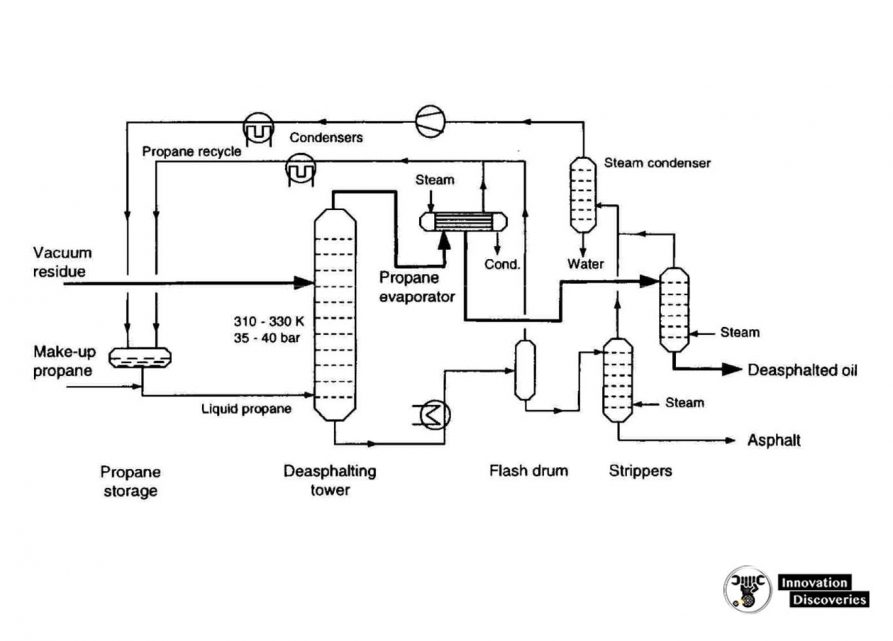
4. Propane deasphalting
- Coke-forming tendencies of heavier distillation products are reduced by the removal of asphaltenic materials by solvent extraction.
- Liquid propane is a good solvent (butane and pentane are also commonly used).
- Deasphalting is based on the solubility of hydrocarbons in propane.
- Vacuum residue is fed to a countercurrent deasphalting tower.
- Alkanes dissolve in propane whereas asphaltenic materials (aromatic compounds), and ‘coke-precursors’ do not.
- Asphalt is sent for thermal processing.
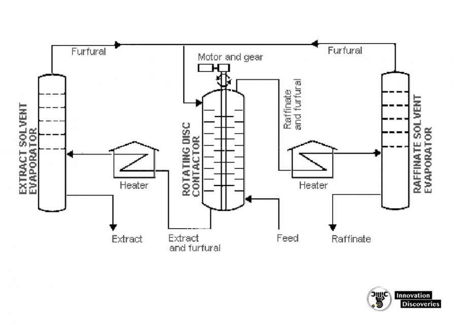
5. Solvent extraction and dewaxing
- Solvent treating is a widely used method of refining lubricating oils as well as a host of other refinery stocks.
- Since distillation (fractionation) separates petroleum products into groups only by their boiling-point ranges, impurities may remain.
These include:
- Organic compounds containing sulfur, nitrogen, and oxygen
- Inorganic salts
- Dissolved metals
- Soluble salts that were present in the crude feedstock
- In addition, kerosene and distillates may have trace amounts of aromatics and naphthenes, and lubricating oil base-stocks may contain wax.
- Solvent refining processes including solvent extraction and solvent dewaxing usually remove these undesirables at intermediate refining stages or just before sending the product to storage.
- The purpose of solvent extraction is to prevent corrosion, protect catalysts in subsequent processes, and improve finished products by removing unsaturated, aromatic hydrocarbons from lubricant and grease stocks.
- The solvent extraction process separates aromatics, naphthenes, and impurities from the product stream by dissolving or precipitation.
- The feedstock is first dried and then treated using a continuous countercurrent solvent treatment operation.
- In one type of process, the feedstock is washed with a liquid in which the substances to be removed are more soluble than in the desired resultant product.
- In another process, selected solvents are added to cause impurities to precipitate out of the product.
- In the adsorption process, highly porous solid materials collect liquid molecules on their surfaces.
- The solvent is separated from the product stream by heating, evaporation, or fractionation, and residual trace amounts are subsequently removed from the raffinate by steam stripping or vacuum flashing.
- The most widely used extraction solvents are phenol, furfural, and acrylic acid.
- Other solvents less frequently used are liquid sulfur dioxide, nitrobenzene, and 2,2′ chloroethyl ether.
- The selection of specific processes and chemical agents depends on the nature of the feedstock being treated, the contaminants present, and the finished product requirements.
An aromatic solvent extraction unit
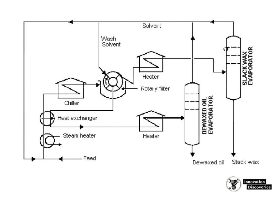
Solvent Dewaxing
- Solvent dewaxing is used to remove wax from either distillate or residual basestock at any stage in the refining process.
- There are several processes in use for solvent dewaxing, but all have the same general steps, which are:
- Mixing the feedstock with a solvent;
- Precipitating the wax from the mixture by chilling
- Recovering the solvent from the wax and dewaxed oil for recycling by distillation and steam stripping.
- Usually, two solvents are used: toluene, which dissolves the oil and maintains fluidity at low temperatures, and methyl ethyl ketone (MEK), which dissolves little wax at low temperatures and acts as a wax precipitating agent.
- Other solvents sometimes used include benzene, methyl isobutyl ketone, propane, petroleum naphtha, ethylene dichloride, methylene chloride, and sulfur dioxide.
- In addition, there is a catalytic process used as an alternative to solvent dewaxing.
Solvent dewaxing unit
6. Blending
Blending is the physical mixture of a number of different liquid hydrocarbons to produce a finished product with certain desired characteristics.
Products can be blended in-line through a manifold system, or batch blended in tanks and vessels.
An in-line blending of gasoline, distillates, jet fuel, and kerosene is accomplished by injecting proportionate amounts of each component into the mainstream where turbulence promotes thorough mixing.
Additives including octane enhancers, anti-oxidants, anti-knock agents, gum and rust inhibitors, detergents, etc. are added during and/or after blending to provide specific properties not inherent in hydrocarbons.
CRUDE DISTILLATION UNIT PRODUCTS
Fuel gas.
- The fuel gas consists mainly of methane and ethane. In some refineries, propane in excess of LPG requirements is also included in the fuel gas stream. This stream is also referred to as ‘‘dry gas.’’
Wet gas.
- The wet gas stream contains propane and butanes as well as methane and ethane. The propane and butanes are separated to be used for LPG and, in the case of butanes, for gasoline blending and alkylation unit feed.
LSR naphtha.
- The stabilized LSR naphtha (or LSR gasoline) stream is desulfurized and used in gasoline blending or processed in an isomerization unit to improve octane before blending into gasoline.
HSR naphtha or HSR gasoline.
- The naphtha cuts are generally used as catalytic reformer feed to produce high-octane reformate for gasoline blending and aromatics.
Gas oils.
- The light, atmospheric, and vacuum gas oils are processed in a hydrocracker or catalytic cracker to produce gasoline, jet, and diesel fuels. The heavier vacuum gas oils can also be used as feedstocks for lubricating oil processing units.
Residuum.
- The vacuum still bottoms can be processed in a visbreaker, coker, or deasphalting unit to produce heavy fuel oil or cracking and/or lube base stocks. For asphalt crudes, the residuum can be processed further to produce road and/or roofing asphalt.
DISCOVER MORE:

DOWNLOAD: HEAVY EQUIPMENT SYSTEMS | PDF
LEAD ACID VS. LITHIUM CAR BATTERY: WHAT’S THE DIFFERENCE?
Visit Forum
Visit Our Friendly Website
Image source: FES Tanks