A torque converter is a type of fluid coupling used to transfer rotating power from the engine of a vehicle to the transmission.
It takes the place of a mechanical clutch in an automatic transmission. The main function of it is to allow the load to be isolated from the main power source.
It sits in between the engine and transmission. It has the same function as the clutch in the manual transmission.
As the clutch separates the engine from the load when it stops, in the same way, it also isolates the engine from a load and keeps engine running when the vehicle stops.
Cars with automatic transmissions don’t have clutches, so they need a way to let the engine keep running while the wheels and gears in the transmission come to a stop.
Manual transmission cars use a clutch that disconnects the engine from the transmission.
Automatic transmissions use a torque converter.
When the engine is idling, such as at a stoplight, the torque amount going through the torque converter is small but still enough to require some pressure on the brake pedal to stop the car from creeping.
When you release the brake and step on the gas, the engine speeds up and pumps more fluid into the torque converter, causing more power (torque) to be transmitted to the wheels.
FUNCTIONS OF TORQUE CONVERTER
It’s main functions are:
- It transfers the power from the engine to the transmission input shaft.
- Drives the front pump of the transmission.
- Isolates the engine from the load when the vehicle is stationary.
- It multiplies the torque of the engine and transmits it to the transmission.
It almost doubles the output torque.
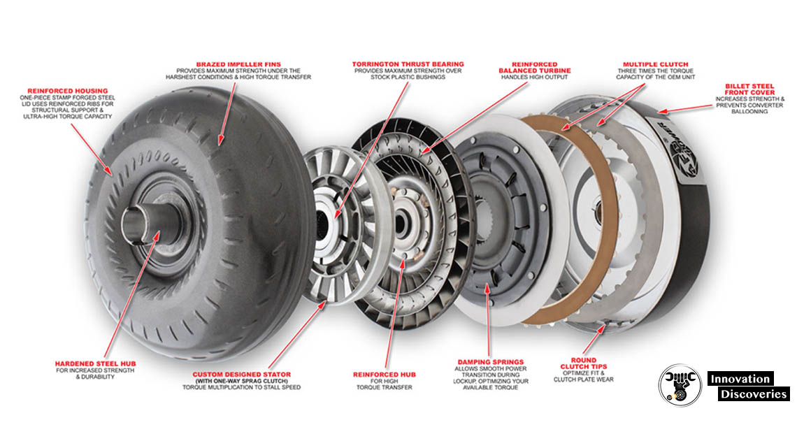
PARTS OF TORQUE CONVERTER
The torque converter has three main parts
1. Impeller or Pump
The impeller is connected to the housing and the housing connected to the engine shaft. It has curved and angled vanes.
It rotates with the engine speed and consists of automatic transmission fluid.
When it rotates with the engine, the centrifugal force makes the fluid move outward.
The impeller’s blades are designed so that it directs the fluid towards the turbine blades. It acts as a centrifugal pump which sucks the fluid from the automatic transmission and delivers it to the turbine.
2. Stator
The stator is located between the impeller and turbine.
The stator’s main function is to give direction to the returning fluid from the turbine so that the fluid enters the impeller in the direction of its rotation.
As the fluid enters in the direction of the impeller, it multiplies the torque.
So the stator helps in the torque multiplication by changing the direction of the fluid and allows it to enter in the direction of the impeller rotation.
The stator changes the direction of fluid almost up to 90 degrees.
The stator is mounted with a one-way clutch that allows it to rotate it in one direction and prevent its rotation in other directions.
The turbine is connected to the transmission system of the vehicle. And the stator is placed in between the impeller and turbine.
3. Turbine
The turbine is connected to the input shaft of the automatic transmission. It is present on the engine side.
It also consists of curved and angled blades. The blades of the turbine are designed so that it can change the direction of the fluid completely that strikes on its blades.
It is the change in the direction of the fluid that forces the blades to move in the impeller’s direction.
As the turbine rotates, the input shaft of the transmission also rotates and makes the vehicle move.
The turbine also has a lockup clutch at its back.
The lockup clutch comes into play when the torque converter achieves the coupling point. the lockup eliminates the loses and improves the efficiency of the converter.
WORKING PRINCIPLE OF TORQUE CONVERTER
For understanding the working principle of a torque converter, let’s take two fans.
One fan is connected to the power source, and the other is not connected with the power source.
When the first fan connected to the power source starts moving, the air from it flows to the second fan, stationary.
The air from the first fan strikes on the second fan’s blades, and it also starts rotating almost at the same speed to the first one.
When the second fan is stopped, it does not stop the first one. The first fan keeps rotating.
On the same principle, the torque converter works.
In that, the impeller or pump acts as the first fan which is connected to the engine and turbine act as the second fan which is connected to the transmission system.
When the engine runs, it rotates the impeller and due to the centrifugal force the oil inside the torque converter assembly directed towards the turbine.
As it hits the turbine blades, the turbine starts rotating.
This makes the transmission system rotate and the wheels of the vehicle move.
When the engine stops, the turbine also stops rotating, but the impeller connected the engine keeps moving, and this prevents the killing of the engine.
It has three stages of operations
1. Stall
During the vehicle’s stall (stop) condition, the engine is applying power to the impeller, but the turbine cannot rotate.
This happens, when the vehicle is stationary, and the driver has kept his foot on the brake paddle to prevent it from moving.
During this condition maximum multiplication of torque takes place.
As the driver removes its foot from the brake paddle and presses the accelerator paddle, the impeller starts moving faster, and this sets the turbine to move.
In this situation, there is a larger difference between the pump and turbine speed. The impeller speed is much greater than the turbine speed.
2. Acceleration:
During acceleration, the turbine speed keeps increasing, but there is still a large difference between the impeller and turbine speed.
As the speed of the turbine increases, the torque multiplication reduces.
During acceleration of the vehicle the torque multiplication is less than that is achieved during a stall condition.
3. Coupling
It was a situation when the turbine achieved approximately 90 per cent of the impeller’s speed, and this point is called the coupling point.
The torque multiplication seizes and becomes zero, and the torque converter behaves just like a simple fluid coupling.
At the coupling point, the lock-up clutch comes into play and locks the turbine to the converter’s impeller.
This puts the turbine and impeller to move at the same speed.
The lock-up clutch engages only when the coupling point is achieved.
During coupling, the stator also starts to rotate in the direction of the impeller and turbine rotation.
NOTE:
1. The maximum torque multiplication takes place during the stalling condition.
2. The stator remains stationary before the coupling point and helps in the torque multiplication. As the coupling attained, the stator stops torque multiplication and starts rotating with the impeller and turbine.
3. The lock-up clutch engages when the coupling point is achieved and removes the power losses resulting in increased efficiency.
TYPES OF TORQUE CONVERTER
1. Single-Stage Torque Converters
The beauty of single-stage converters is their tough, reliable simplicity.
Each converter consists basically of three elements: the turbine, the stator, and the impeller. Single-stage converters come in two types of housing — stationary and rotating.
Depending on the model, single-stage torque converters boast various capabilities: Sumpless single-stage converters with PTO drives are ideal for applications with power-shift transmissions and driving auxiliary hydraulic pumps.
High-torque ration converters with stationary housing feature extraordinary hoisting and lowering capabilities.
Type Four hydraulic converters are designed specifically for the oil and gas industry.
2. Three Stage Torque Converters
Three-stage torque converters employ three rings of turbine blades and two sets of reactors or stator blades.
This design’s effect is increased torque — up to five times the amount of engine output torque, in fact, when the engine is at a stall.
Depending on the specific design, three-stage converters are rated for a range of engines, including 335 hp at 2400 rpm, 420 hp at 2200 rpm, and 580 hp at 2,200 rpm.
Three-stage converters also come with both stationary and rotating housing.
Advantages
- Produces the maximum torque as compared with the vehicle equipped with a clutch.
- Removes the clutch pedal.
- It makes the job of driving a vehicle easier.
Disadvantages
- Its fuel efficiency is low as compared with the vehicle with manual transmission.
Application
- The torque converter is used in the vehicle that is equipped with automatic transmission. It is also used in industrial power transmissions such as conveyor drives, winches, drilling rigs, almost all modern forklifts, construction equipment, and railway locomotives.
- It is used in marine propulsion systems.


6 Comments