The vehicle is equipped with many electrical devices to drive safely and comfortably. The vehicle requires electricity not only while driving but also while it stops.
Therefore, the vehicle has a battery for a power supply and a charging system to generate electricity by the engine running. The charging system supplies electricity to all the electrical devices and charges the battery.
The Charging system is an important part of the electrical system. It provides electrical current for the lights, the radio, the heater, the engines electrical systems, and other electrical accessories. It also maintains the batteries in a charged state, recharging them as necessary.
The charging system has three main components: the alternator, the voltage regulator, and the batteries.
The alternator generates electrical power to run accessories and to
recharge the batteries. It is normally driven by a belt located off the
crankshaft. Mechanical energy from the crankshaft is converted by the
alternator into electrical energy for the batteries and accessories.
The voltage regulator acts as an electrical traffic cop to control the
alternator output. It senses when the batteries need recharging, or when
the vehicles electrical needs increase and adjust the alternator’s
output accordingly.
The batteries are a reservoir of chemical electrical power. Their primary purpose is to crank the engine. They also supply power to vehicle accessories when the electrical load is too great for the alternator alone.
Three-phase alternating current
(1) When a magnet rotates within a coil, a voltage will be created
between both ends of the coil. This will give rise to an alternating
current.
(2) The relation between the current generated in the coil
and the position of the magnet is as shown in the figure. The largest
amount of current is generated when the N and S poles of the magnet are
closest to the coil. However, the current flows in the opposite
direction with each half-turn of the magnet. Current that forms a sine
wave in this manner is called “single-phase alternating current”.
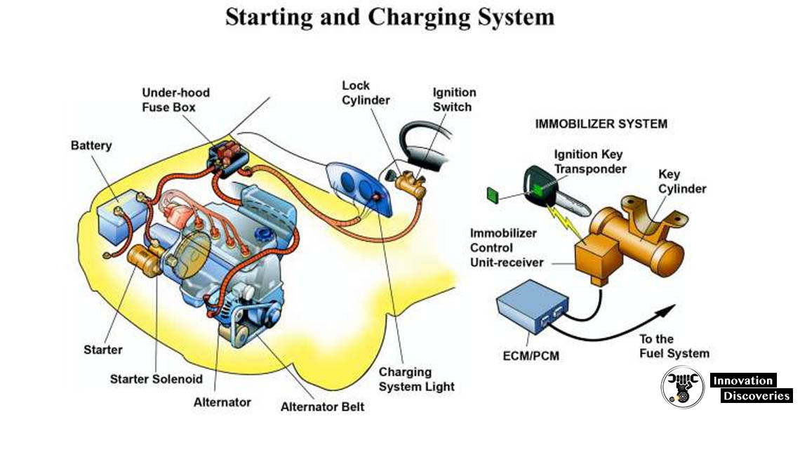
COMPONENTS AND FUNCTIONS
In general, the components of the charging system are composed of alternators and regulators. However, the charging system needs to add some additional components so that the electricity generated can be supplied to the battery and to all electrical loads safely and precisely. The component, consisting of;
1. Battery
The function of the battery is as a storage of electrical energy. Like a warehouse, the battery will store all the electrical energy generated by the alternator and then this stored electricity is removed when necessary.
2. Fuse and Fusible links
Fuse and fusible links have different functions even though have the same shape. The fusible link can be called as the main fuse which is placed near the battery positive terminal. The function of this fuse is to protect the entire electrical system of the car from excessive currents. Generally, the fusible link has a capacity of up to more than 60 Ampere.
While the function of the fuse is as the safety of a series of specific electrical wiring, in conventional charging system there are two fuses with the same capacity (it’s about 10-15 Ampere). A fuse is used as a voltage regulator fuse and another fuse is used to secure the CHG and Voltage relay.
3. CHG Lights
CHG lamp or commonly also called “charging warning light” is an indicator light to indicate the present failure of the charging system. When the ignition key ON then this light will light up normally, as well as when the engine life of this lamp should turn on, if it is dead then it could mean the charging system failure.
4. Ignition key
The ignition key works as a switch. The charging system will be activated automatically when the engine is running, but to generate a magnetic field on the rotor coil must be done by a switch.
The ignition switch is used as a switch to connect and disconnect power (positive battery current) from battery to rotor coil. When the ignition key is ON, then the electricity from the battery to the coil rotor will be connected. However, when the ignition key is turned OFF then the power supply will be cut off. So it is not possible the alternator generates electricity when the ignition key is OFF even the engine crankshaft rotates.
5. Regulator
The function of the regulator is to regulate the voltage generated by the alternator. Why should it be there? because the voltage generated by the alternator depends on the engine’s RPM. This means that if the engine RPM is low, the alternator voltage is also low, but if the engine RPM is high then the alternator voltage is also high.
The regulator will be used to keep the voltage generated by the alternator not exceeding 14 volts even if the engine run in high RPM. This voltage setting aims to protect the electrical components of the vehicle to prevents over-voltage.
There are two types of regulators, namely type or conventional type and type of IC. The point type/conventional uses two coils to adjust the alternator output voltage. While the IC Regulator uses an IC circuit (Integrated Circuit) to regulate the output voltage.
6. Altenator
The function of the alternator is to convert a partial engine’s rotating energy into electricity. The alternator input comes from the engine pulley connected through a V belt, the rotation of the rotor will cause the intersection of the magnetic force line with the stator coil so that the electrons flow on the stator coil.
The electricity in the stator coil is not directly connected to the battery, but it must pass through the diode bridge to rectify the current. This is done because the current in the stator coil is AC (Alternate Current).
7. Charging Wire
The function of the charging wire is to connect every component of the charging system, there are at least two types of wires: standard wire and B + wire. The standard wire has a small diameter like the car’s electrical wiring in general, the function of this wire is connecting each terminal on the entire charging system.
While the B + wire has a larger diameter than the standard wire and almost matches the stater wire. The function of this wire is to connect the terminal B alternator with Battery.

Well Explained and it’s really helping