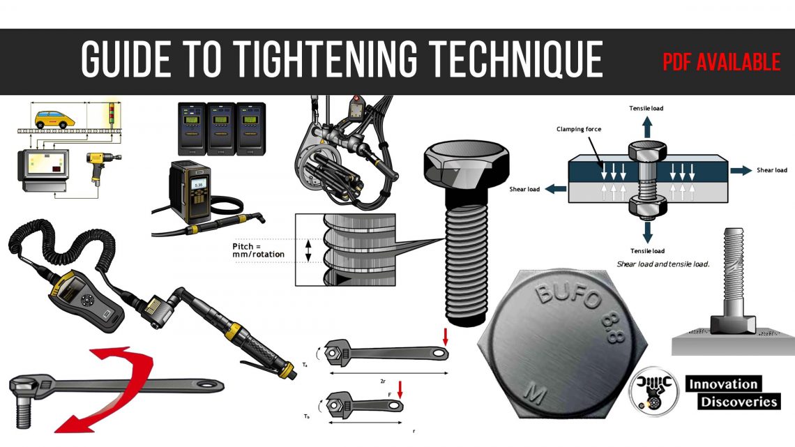
POCKET GUIDE TO TIGHTENING TECHNIQUE
This article provides an introduction to the technique of using threaded fasteners for assembling components, the application of power tools for the assembly, and the influence of tool selection on the quality of the joint.
1. WHY THREADED FASTENERS?
There are several ways of securing parts and components to each other, e.g. gluing, riveting, welding, and soldering.
However, by far the most common method of joining components is to use a screw to clamp the joint members with a nut or directly to a threaded hole in one of the components.
The advantages of this method are the simplicity of design and assembly, easy disassembly, productivity, and in the end – cost.
2. THE SCREW JOINT
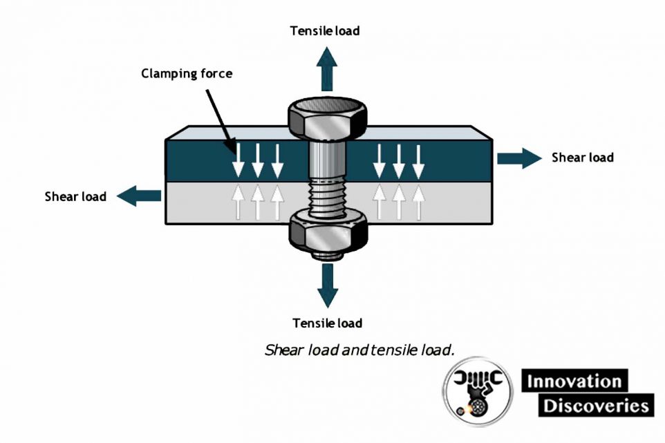
A screw is exposed to tensile load, torsion, and sometimes also to a shear load.
The stress in the screw when the screw has been tightened to the design extent is known as the pre-stress.
The tensile load corresponds to the force that clamps the joint members together. External loads which are less than the clamping force will not change the tensile load in the screw.
On the other hand, if the joint is exposed to higher external loads than the pre-stress in the bolt the joint will come apart and the tensile load in the screw will naturally increase until the screw breaks.
Torsion in the screw results from friction between the threads in the screw and the nut.
Some screws are also exposed to shear loads which occur when the external force slides the members of the joint in relation to each other perpendicular to the clamping force.
In a properly designed joint the external shear force should be resisted by the friction between the components.
A joint of this kind is called a friction joint. If the clamping force is not sufficient to create the friction needed, the screw will also be exposed to the shear load.
Joints are frequently designed for a combination of tensile and shear loads.
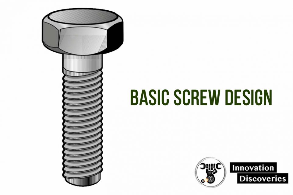
The screw is made up of the shank and the head.
The shank is threaded, either for part of its length or for the full length from the end to the head. Longer screws are usually only partly threaded.
There is no need to make a thread longer than is necessary to tighten the joint as this will only make the screw more expensive and reduce the tensile strength.
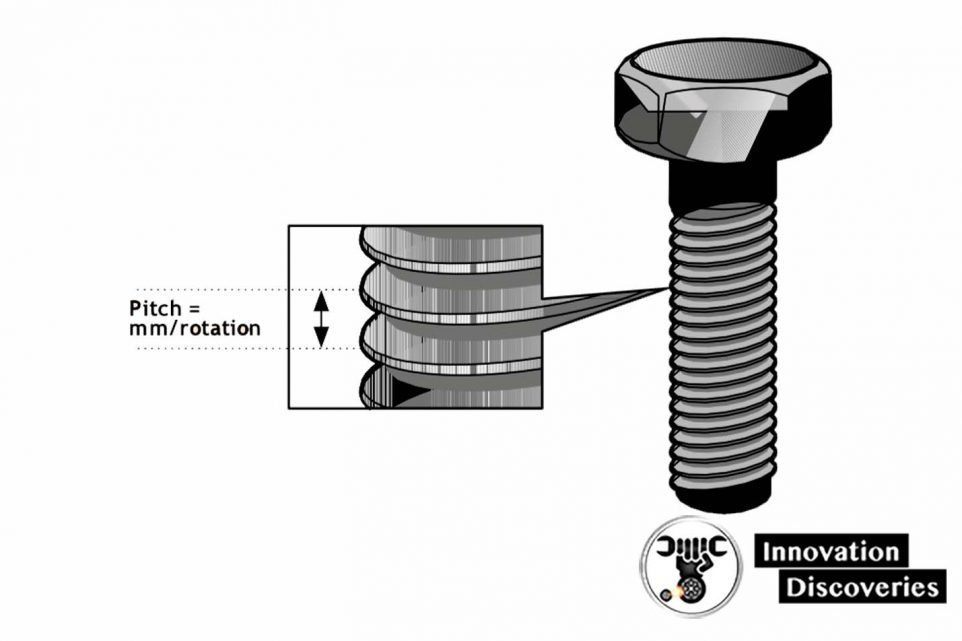
The dimensions of threads, the shape of the thread, and the pitch, i.e. the distance between successive threads, have been standardized.
In practice, there are only two different standards used today in the industry; the Unified standard UN, originally used in the Anglo-Saxon countries, and the European Metric standard M.
Apart from the basic dimensional differences the UN and M standards have different angles and depths of thread.
Both standards include separate specifications for fine threads. The UN fine thread standard UNF is quite a common parallel to the normal UNC type.
3. CLAMPING FORCE
In general, it is desirable that the screw is the weakest member of the joint.
An over-dimensioned screw makes the product both heavier and unnecessarily expensive.
As a standard screw is usually comparatively inexpensive it is preferable that the screw should be the first part to break.
Furthermore, in most cases, the dimensions of the screw are not critical for the quality of the joint.
What is decisive is the clamping force, i.e. whether it is sufficient to carry all the load for which the joint is designed, and whether the joint will remain tight enough to prevent loosening if exposed to pulse loads.
The problem is that there is no practical way to measure the clamping force in normal production situations.
Consequently, the value of the clamping force is usually referred to as the tightening torque.
As the clamping force is a linear function of both the turning angle of the screw and the pitch of the thread, there is a direct relation between the clamping force and the tightening torque within the elastic range of the screw elongation.
However, only about 10% of the torque applied is transferred into clamping force.
The remaining tightening force is consumed in friction in the screw joint – 40% of the torque to overcome the friction in the thread and 50% in friction under the screw head.
4. EFFECT OF LUBRICATION
If a screw is lubricated, the friction in the threads and under the head is decreased and the relation between tightening torque and clamping force is changed.
If the same torque is applied as before lubrication, a lot more torque will be transformed into clamping force.
At worst this might lead to the tension in the screw exceeding the tensile strength and breaking of the screw.
On the other hand, if the screw is completely dry of lubricant the clamping force might be too small to withstand the forces for which the joint is designed, with the risk that the screw becomes loose.
| Bolt Material | Nut Material | Dry | Lightly Oiled |
|---|---|---|---|
| Untreated | Untreated | 0.18-0.35 | 0.14-0.26 |
| Phosphorous coated | Untreated | 0.25-0.40 | 0.17-0.30 |
| Electro Zinc plated | Untreated | 0.11-0.36 | 0.11-0.20 |
| Phosphorous coated | Phosphorous coated | 0.13-0.24 | 0.11-0.17 |
| Electro Zinc plated | Electro Zinc plated | 0.18-0.42 | 0.13-0.22 |
5. SCREW QUALITY CLASSIFICATION
When a screw is tightened and the clamping force starts to build up, the material of the screw is stressed.
After a short time when the thread settles the material will stretch in proportion to the force.
In principle, this elongation will continue until the stress in the screw is equal to the tensile strength at which the screw will break.
However, as long as the elongation is proportional to the stress the screw will regain its original length when the load is removed. This is known as the elastic area.
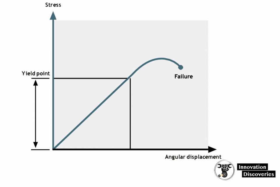
At certain stress, known as the yield point, plastic deformation of the material in the screw will occur.
However, the screw will not break immediately. Torque will continue to increase but at a lower torque rate during the deformation above the yield point.
The plastic deformation will result in a permanent elongation of the screw if the joint is loosened.
For very accurate clamping force requirements this area is sometimes deliberately specified for the tightening process. Beyond the plastic area, breakage occurs.
M-Threaded screwbolts
Tightening torque Nm, according to ISO 898/1
The material qualities of screws are standardized, i.e. the amount of tensile stress they can be exposed to before the yield point is reached and before breakage occurs.
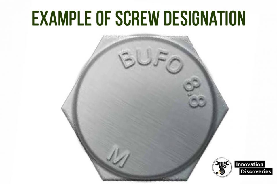
All screws should be marked according to their Bolt Grade – a classification standard in a two-digit system where the first digit refers to the minimum tensile strength in 100 N/mm 2 and the second digit indicates the relation between the yield point and the minimum tensile strength.
For example:
Bolt Grade 8.8 designates a screw with 800 N/mm 2 minimum tensile strength and a yield point of 0.8 x 800 = 640 N/mm 2.
| Thread | 3.6 | 4.6 | 4.8 | Bolt grade 5.8 Nm | 8.8 | 10.9 | 12.9 |
|---|---|---|---|---|---|---|---|
| M1.6 | 0.05 | 0.065 | 0.086 | 0.11 | 0.17 | 0.24 | 0.29 |
| M2 | 0.10 | 0.13 | 0.17 | 0.22 | 0.35 | 0.49 | 0.58 |
| M2.2 | 0.13 | 0.17 | 0.23 | 0.29 | 0.46 | 0.64 | 0.77 |
| M2.5 | 0.20 | 0.26 | 0.35 | 0.44 | 0.70 | 0.98 | 1.20 |
| M3 | 0.35 | 0.46 | 0.61 | 0.77 | 1.20 | 1.70 | 2.10 |
| M3.5 | 0.55 | 0.73 | 0.97 | 1.20 | 1.90 | 2.70 | 3.30 |
| M4 | 0.81 | 1.10 | 1.40 | 1.80 | 2.90 | 4.00 | 4.90 |
| M5 | 0.60 | 2.20 | 2.95 | 3.60 | 5.70 | 8.10 | 9.70 |
| M6 | 2.80 | 3.70 | 4.90 | 6.10 | 9.80 | 14.0 | 17.0 |
| M8 | 8.90 | 10.50 | 15.0 | 24.0 | 33.0 | 40.0 | |
| M10 | 17.0 | 21.0 | 29.0 | 47.0 | 65.0 | 79.0 | |
| M12 | 30.0 | 36.0 | 51.0 | 81.0 | 114.0 | 136.0 | |
| M14 | 48 | 58 | 80 | 128 | 181 | 217 | |
| M16 | 74 | 88 | 123 | 197 | 277 | 333 | |
| M18 | 103 | 121 | 172 | 275 | 386 | 463 | |
| M20 | 144 | 170 | 240 | 385 | 541 | 649 | |
| M22 | 194 | 230 | 324 | 518 | 728 | 874 | |
| M24 | 249 | 295 | 416 | 665 | 935 | 1120 | |
| M27 | 360 | 435 | 600 | 961 | 1350 | 1620 | |
| M30 | 492 | 590 | 819 | 1310 | 1840 | 2210 | |
| M36 | 855 | 1030 | 1420 | 2280 | 3210 | 3850 | |
| M42 | 1360 | 2270 | 3610 | 5110 | 6140 | ||
| M45 | 1690 | 2820 | 4510 | 6340 | 7610 | ||
| M48 | 2040 | 3400 | 5450 | 7660 | 9190 |
6. JOINT TYPES
Screw joints vary not only in size but also in type, which changes the characteristics of the joints.
From a tighten- ing point of view the most important quality of a joint is the “hardness”.
In the figures, this can be defined as the “torque rate”, which is the tightening angle necessary to achieve the recommended torque of the screw dimension and quality in question measured from the snug level – the point at which the components and the screw head become tight.
The torque rate can vary considerably for the same diameter of the screw.
A short screw clamping plain metal components reaches the rated torque in only a fraction of a turn of the screw. This type of joint is defined as a “hard joint”.
A joint with a long screw that has to compress soft components such as gaskets or spring washers require a much wider angle, possibly even several turns of the screw or nut to reach the rated torque.
This type of joint is described as a soft joint. Obviously, the two different types of joints behave differently when it comes to the tightening process.
7. TORQUE AND ANGLE
As mentioned above, the tightening torque is for practical reasons the criteria normally used to specify the pre-stress in the screw.
The torque, or the moment of force, can be measured either dynamically, when the screw is tightened, or statically, by checking the torque with a torque wrench after tightening.
Torque specifications vary considerably depending on the quality demands of the joint.
A safety-critical joint in a motor car, such as the wheel suspension, cannot be allowed to fail and is consequently subject to very stringent tolerance requirements.
On the other hand, a nut for securing the length of a workbench height adjustment screw is not regarded as critical from a clamping force point of view and no torque requirement may be specified.
A higher level of quality control is reached by adding the tightening angle to the measured parameters.
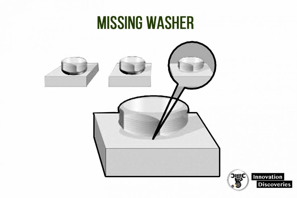
In the elastic area of the screw, this can be used to verify that all the members of a joint are present, e.g. that a gasket or a washer is not missing.
Also, the screw quality can be verified by measuring the tightening angle, before snug level as well as for final torque-up.
In sophisticated tightening processes the angle can also be used to define the yield point and allow tightening into the plastic area of the screw.
8. MEASUREMENT METHODS
Knowing the tightening specifications for a screw joint the obvious question is; how does one know that the joint has been properly tightened?
Torque measurements are made according to one of two measurements or dynamic measurements.
Principles – static
Static measurement means that the tightening torque is checked after the tightening process has been completed.
The measurement is usually done by hand with a torque wrench which has either a spring-loaded torque scale or a strain gauge transducer activated instrument.
A very common method for checking the tightening torque is to use a click wrench, which is a torque wrench equipped with a clutch that can be pre-adjusted to a specific torque.
If the torque is greater than the preset torque value the clutch will release with a click.
If the torque is less, the final torque-up is possible until the wrench clicks. Over-tightening cannot be detected with the click wrench.
To measure the static torque the torque value must be read instantly as the screw starts to turn.
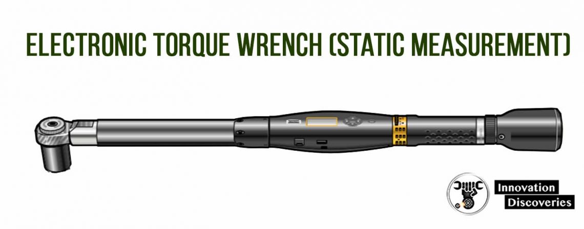
An electronic torque wrench can be used for a more sophisticated static measurement of the joint.
The tool has a strain gauge torque transducer which gives a high level of accuracy.
Dynamic measurement on the other hand means that the torque is continuously measured during the complete tighten- ing cycle.
This is usually the preferred method in production where power tools are used for tightening.
The advantage over the static method is that dynamic measurement provides an indication of the tightening tool performance without the influence of relaxation in the joint and variations in resting friction.
It also eliminates the necessity for subsequent checking.
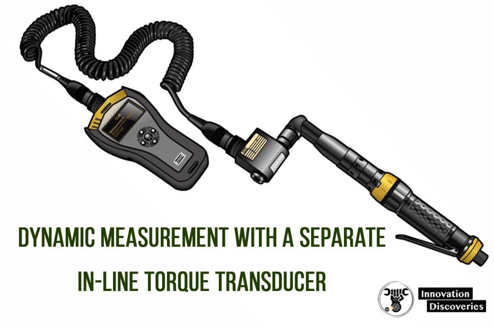
Dynamic measurement is done either directly by measuring with a built-in or a separate in-line torque transducer, or indirectly by current measurement of some sophisticated electric-powered screwdrivers and nut runners.
In both cases, torque measuring is only possible where the tools have direct torque transmission, i.e. not a pulsating force as is the case with impact wrenches and pulse nutrunners.
The in-line torque transducer is mounted between the driving shaft of the tool and the screw drive socket orbit.
It is a drive rod with installed resistances, a so-called Wheatstone Bridge, which senses the elastic deformation of the body as a result of the torque applied and produces an electric signal that can be processed in a measuring instrument.
In-line transducers are also available with a built-in angle encoder for monitoring the tightening angle.
As the housing with its connector for the signal cable has to be held to prevent it from rotating, the in-line transducer is not practical for use in continuous monitoring in serial production.
However, for tool installation and torque setting, and online quality checking, the in-line transducer is the instrument commonly used for reading the applied torque values.
In assembly line production where tightening requires 100% monitoring or if the tightening process itself is controlled by the torque readings, the torque transducer is usually built into the tightening tool.
In geared tools, there are several positions where the transducer can be installed, but for dimensional reasons, it is advantageous to place it as close to the motor as possible where the forces involved are the lowest.
Instead of putting the strain gauges on the shaft, as with the in-line model, the built-in torque transducer can utilize the reaction forces in the power train assembly of the tool.
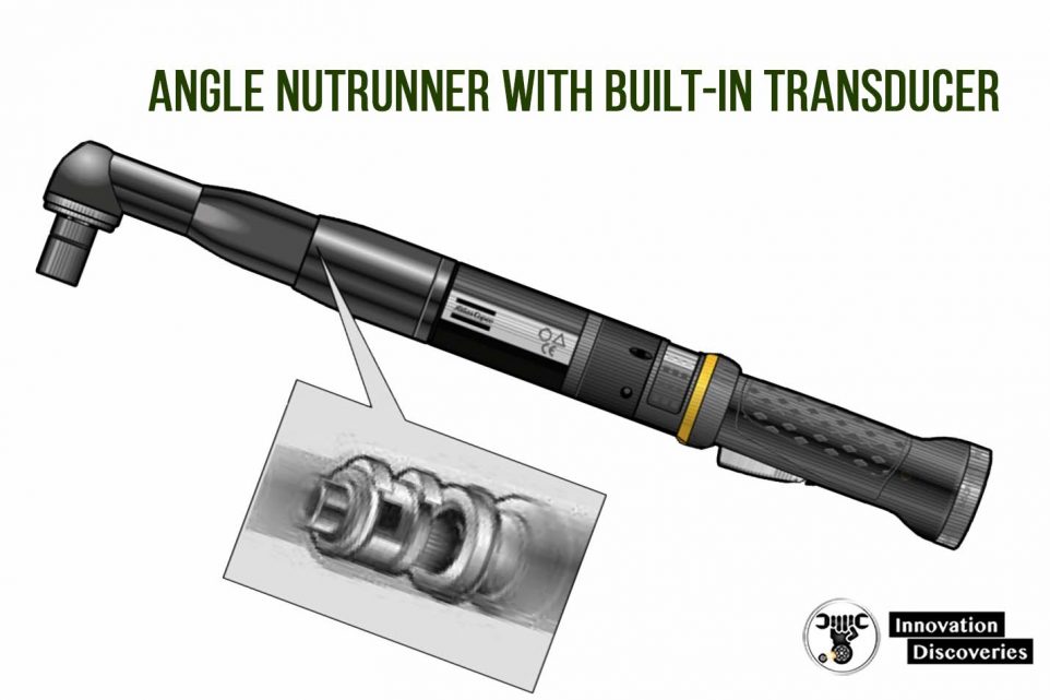
Angle encoders can also be incorporated in the tool design for registration of the joint characteristics during tightening or advanced tightening control.
9.THE TIGHTENING PROCESS
The tightening process also has a major influence on the quality of the screw joint.
A joint tightened by hand behaves completely differently from one tightened using a power tool.
Also, different types of tools have a decisive influence on the result.
Direct-driven tools such as screwdrivers and nut- runners have a maximum capacity that is decided by the power output of the motor and gear ratio.
They can be of the stall type, where final torque is determined by the torque produced when the tool has no more capacity to overcome the resistance to turn the screw.
Nowadays they are usually equipped with a device that stops the tightening at a predetermined torque.
There are also other types of tightening tools common in industrial production today, i.e. impact wrenches and pulse nutrunners where the motor power is converted to torque output by charging and discharging the energy intermittently during the process.
This means that very powerful tools can be designed with limited weight and size and with almost no reaction torque to the operator.
However, from a torque monitoring point of view, these types do not lend themselves to dynamic measurement and are, consequently, not discussed in this context.
10. MEAN SHIFT
The fundamental reason for using a power tool for tightening a screw joint is to shorten the processing time within the ability of the operator and quality requirements.
It follows that a high rotational speed of the tool is of prime interest.
Most assembly tools are powered by a motor which gives a high speed during the run-down of the screw when the resistance is low and slows down as the torquing up proceeds.
On hard joints, there is an almost immediate brake from idling speed to stall or shut-off speed.
However, due to the inertia of all the rotating parts, there is quite a lot of dynamic energy stored in the tool, the socket or power bit, and the screw itself.
This energy has to be discharged somehow and most of it is delivered to the joint in the form of added torque, so-called “over-shoot”.
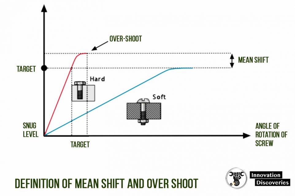
If the joint looked the same all the time there would not be a problem, but if the same tool is run on a soft joint, requiring much more time and energy to build up the torque, the dynamic effects are only marginal.
The result is a difference in torque between the hard and the soft joint which can be considerable. This difference is called the “mean shift”.
In tools equipped with some kind of shut-off device the quality of the clutch also becomes decisive for the mean shift of the tool.
As the tightening sequence is usually very short the time necessary for the clutch to react on the torque impulse will have an equally important influence on the final torque as the dynamic effect, i.e. the shut-off delay gives a much higher torque over-shoot on the hard joint than on the soft.
11. STANDARDS FOR MEASUREMENT
The variations in tightening torque that depends on joint hardness have made it necessary to establish common measurement standards to define the capability of a tool to meet certain quality specifications and to be able to compare different tool types with the specifications.
The common standard used today is ISO 5393 – “Rotary tools for threaded fasteners Performance and test method”.
The standard and the principles for evaluation of the results are discussed in the “Pocket guide to statistical analysis of tightening results”.
12. CERTIFICATION
ISO 5393 represents a common platform for assembly tool manufacturers and users to evaluate the performance of assembly tools.
Based on this measurement standard, many car manufacturers have their quality programs.
These programs involve the categorization as well as quality classification of tools available on the market.
Usually, the performance of a tool, when new as well as after a certain time of operation, must be verified before the tool becomes accepted for use by the manufacturer’s assembly plants worldwide.
The most extensive certification program is the one from the Ford Motor Co.
In principle, it is based on a classification of all the joints in a car in the relevant tool classes with regards to torque requirement.
Tools are tested according to those requirements, from maximum to minimum torque in each class according to the ISO 5393 testing procedure.
For approval, each tool has to meet the accuracy requirements both when new and after 250 000 cycles, and for preferred certification after 500 000 cycles without major repairs and within the same tolerance specification.
Other car manufacturers have similar programs.
Most of them use ISO 5393 as the test method, but demands might vary.
The tests for tool performance are primarily developed by the car manufacturer but the tool manufacturer may be authorized by the user to perform the practical testing.
13. ERRORS IN TIGHTENING
The purpose of monitoring the tightening torque is to ensure that the proper clamping force has been reached.
However, tightening torque alone is not a 100% guarantee that the clamping force is sufficient for the load for which the joint has been designed.
There are a number of errors that might occur and result in inadequate pre-stress in the screw despite the correct tightening torque.
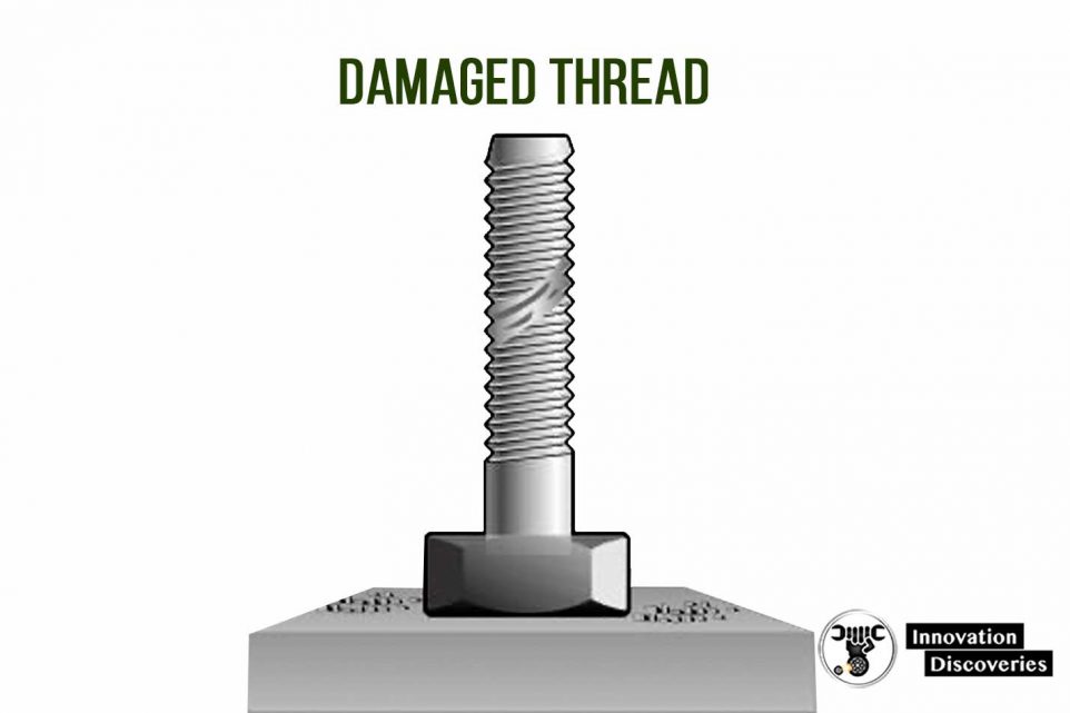
14. DAMAGED THREADS
Damage to the thread or insufficiently cut threads will result in increased resistance to turning the screw and hence the predetermined torque will be reached before the correct clamping force is achieved.
Damaged threads can be detected by monitoring the tightening angle.
15. MISSING JOINT COMPONENTS
A common problem in industrial production is that the operator forgets a washer or packing in the assembly of a joint.
Apart from having other purposes for the design, missing components will change the torque rate of the joint and consequently also the clamping force.
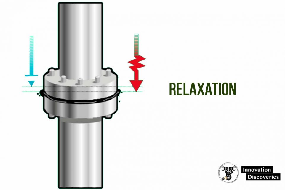
16. RELAXATION
All joints are set after tightening. This means that after a short time, less than 30 milliseconds, the clamping force in the joint is less than it was when the tightening stopped.
For joints that include elastic components such as gaskets, this relaxation can be considerable and a subsequent torque test may show that the torque is just a fraction of the intended specification.
Relaxation is usually overcome by tightening in two stages.
A pulse tool or impact wrench might also be a practical solution as the pulsating drive allows relaxation of the joint between the pulses or impacts.
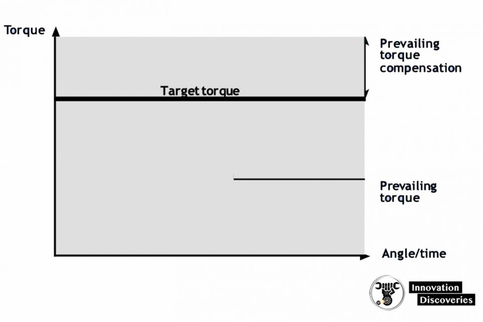
17. PREVAILING TORQUE
Some joints, such as those designed for pre-loading axial bearings in which the wear might in time reduce the prestress necessary to maintain the friction between bolt and nut, have an elastic element installed in the thread that prevents loosening of the joint.
Naturally, this friction element also increases the resistance to turning during tightening and run-down.
A torque control tool might shut off too early as the control device cannot identify the difference between prevailing torque and tightening torque.
The solution is either a device that identifies mechanically when torque-up starts or electronically analyzing the tightening process.
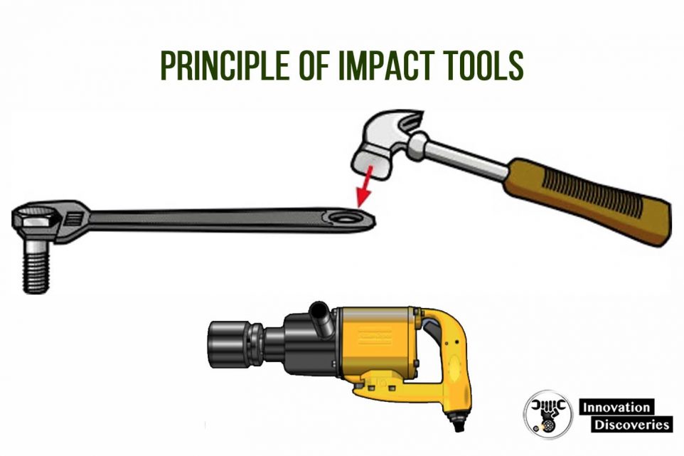
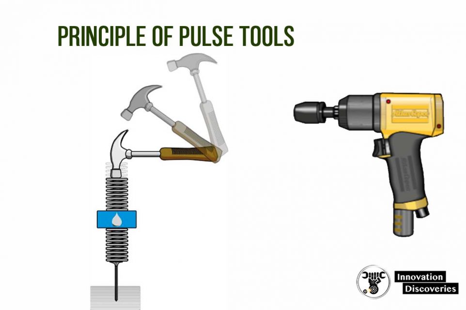
18. TIGHTENING TOOLS
Impact tools
Impact wrenches are based on the same principle as using a hammer to strike a wrench when tightening a bolt or screw, building up torque impact by impact.
In the case of the power impact wrench run by an air motor, the hammer is the combined mass of the rotor and the impact mechanism which delivers their kinetic energy, once or twice per revolution, to the anvil and socket, which represent the wrench in the comparison.
The advantage of impact wrenches is that they have a very high capacity relative to the weight and size of the tool.
As the reaction torque is not greater than that needed to accelerate the hammer the reaction force transferred back to the operator is very small, which makes the impact wrench very flexible and simple to use.
The disadvantages are the comparatively high noise level of the impact wrench and the difficulty in measuring the applied torque and consequently also the limited possibility to achieve accurate torque control.
Consequently, the impact wrench is the ideal tool for loosening rusty and stuck bolts in maintenance work in chemical plants, refineries, and other heavy industries.
Impact wrenches are also suitable for a variety of applications that do not require the highest degree of accuracy.
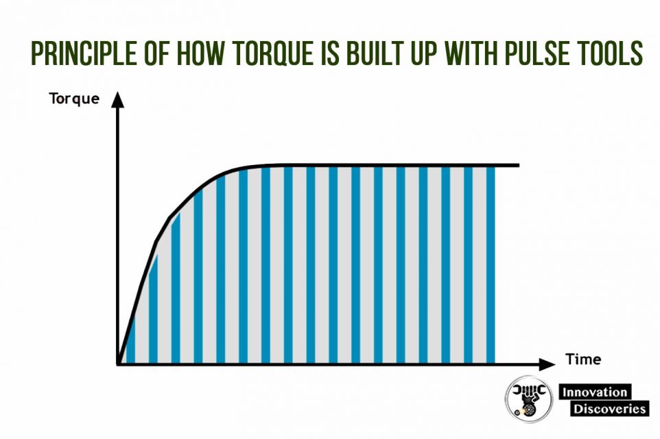
Pulse tools
The hydraulic pulse tool has all the advantages of the impact wrench, i.e. high speed and power from a lightweight and handy tool without reaction forces, but none of the disadvantages except the difficulty of dynamic monitoring of the applied torque.
In pulse tools, the torque is built up, not by metal to metal blows, but via a hydraulic cushion.
This results in low noise, a minimum of vibration, and, above all, good accuracy in tightening.
This is achieved by controlling the hydraulic pressure in the pulse mechanism that limits the torque applied once the pre-set value is reached.
The handiness, speed, low noise, and vibration levels, and torque accuracy have made the pulse tool very popular in the manufacturing industries, including the motor vehicle industry.
The limitation is for applications that require documentation of the applied torque values.
Pneumatic screwdrivers and nut runners
Direct-driven air-powered tools for tightening screws range from the smallest screwdrivers for up to M6 (1/4’’) screw size to high torque nut runners for several thousand Nm tightening torque.
The torque is built up by transforming the power of a high-speed air motor into the low-speed, high-torque output of the driving shaft by gearing. Planetary gears are normally used.
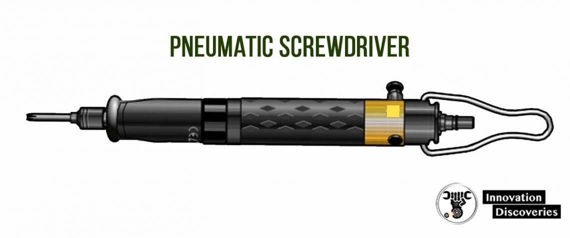
Screwdrivers
The term screwdrivers define those tools used for the smallest screws where the tightening torque required is low enough to allow the reaction torque built up during tightening to be taken up by the operator just by gripping the tool.
In practice this limits the range to between 4 and 12 Nm (M5M6) capacity, depending on the type of tool, the type of joint, and the working position.
The simplest form of screwdriver is the stall type tool in which the applied torque is determined by how much the motor after gearing is capable of tightening before it stops.
Adjustment of torque is made by regulating the air pressure that powers the tool.
Often this type of tool is used for applications with varying torque demand such as sheet metal screws, where the operator stops the tightening process by visual control.
Pneumatic screwdriver.
However, screwdrivers are usually equipped with a torque actuated mechanical clutch.
The clutch can be either of slip type or have a shut-off function. With the slip clutch, a spring-loaded coupling disengages when the pre-set torque is reached but re-engages as long as the trigger is activated.
This is a comparatively inexpensive solution and gives some possibility to add torque or compensate for relaxation but the action is rather noisy and torque control is poor. Shut-off screwdrivers have good accuracy.
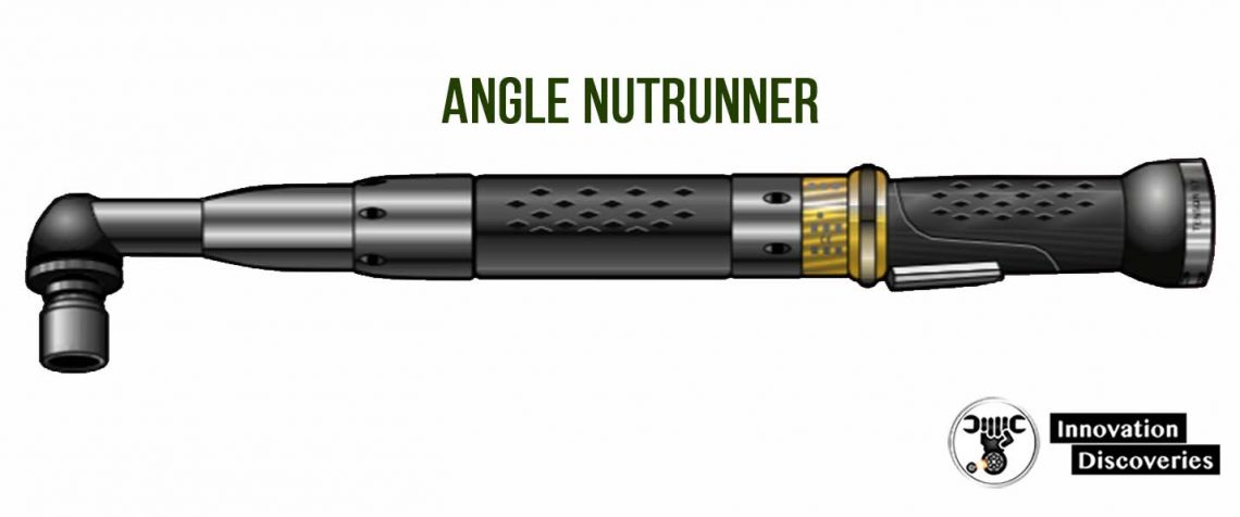
Nutrunners
For a tightening torque above the normal screwdriver range, the reaction torque becomes so high that the operator cannot hold the force with simple straight and pistol grip handles. Some type of reaction bar becomes necessary.
A common type of tool in the range between M6 and M14, i.e. tightening torque 10-150 Nm, is the angle nutrunner where the tool itself is designed to act as a lever to enable the operator to hold the reaction forces.
Pistol grip nutrunners, straight nutrunners, and angle nutrunners for higher torque must be equipped with a fixed reaction bar or an articulated arm to take up the high forces involved.
Direct-driven nutrunners are available as stall-type tools or shut-off models.
They have very good accuracy and lend themselves well to continuous monitoring of torque and tightening angle.
With built-in torque transducers and angle encoders, the tightening process can be controlled and data stored electronically.
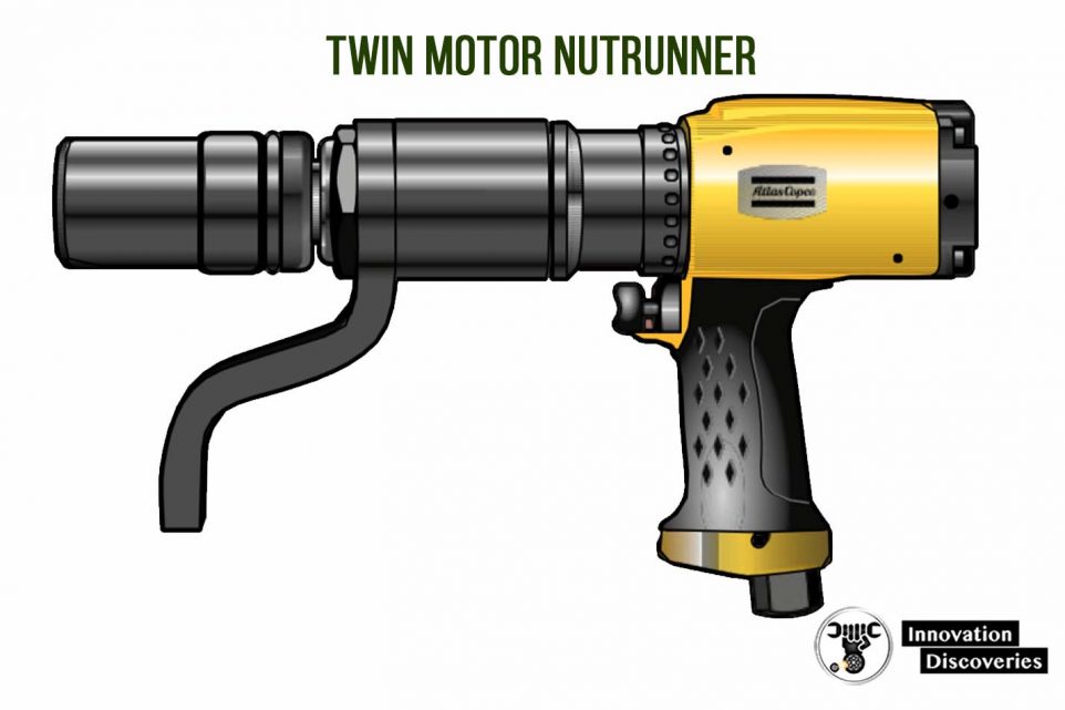
A special type of pistol grip nutrunner is the twin-motor powered high torque nutrunner for up to 1,500 Nm in which one motor via high-speed gearing runs down the bolt and the second, low-geared motor torques up to the final setting.
Models of this type offer fast tightening and a high torque capacity in a very small and handy tool and with excellent accuracy due to the low final speed.
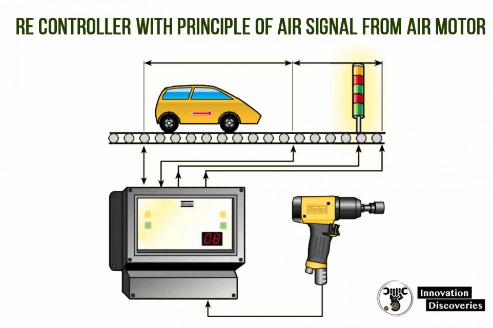
Reporting air signals
A very common fault in assembly-line production is that the operator forgets to tighten a screw in a series of operations.
This can be avoided by counting the completed tightenings and by alarm or line control preventing the mistake from passing unnoticed.
This reporting system is called RE-control and for pneumatic tools, the device consists of a pressure sensor that registers the air pressure variations in the valve system of the tool upon shut-off.
However, due to the difficulties of correctly setting the limits for an OK tightening, nowadays electrical tools are normally used when an OK/NOK signal is needed.
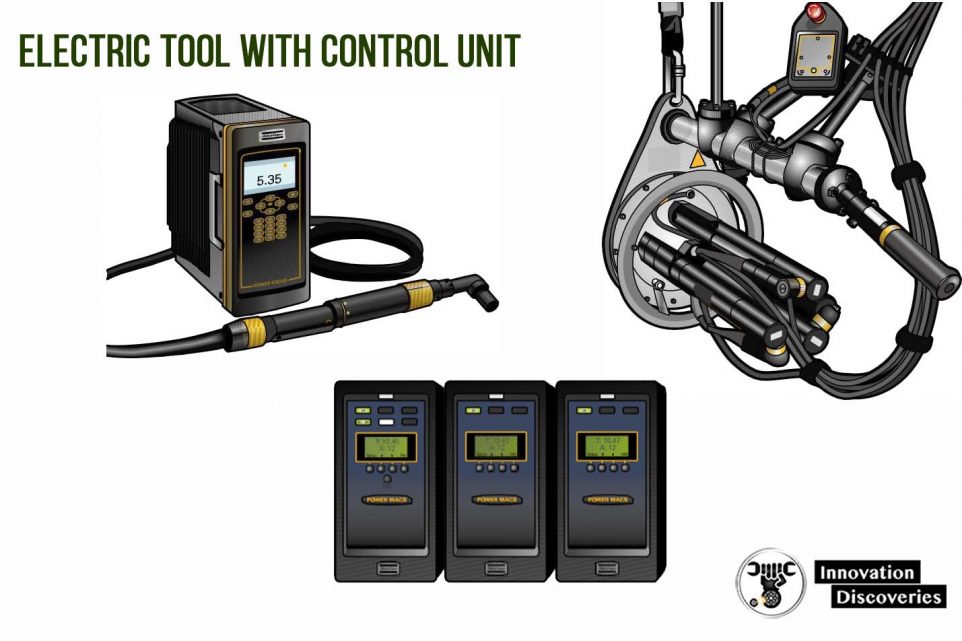
Electric screwdrivers and nut runners
On assembly lines where compressed air is not available or where impurities from the exhaust air must be avoided, electric screwdrivers, mostly powered by a low voltage DC motor via a transformer, are quite common.
Electrically powered screwdrivers and nutrunners are also preferred for motor vehicle assembly and in industries with similar requirements for safety joint control and quality recording.
These are highly sophisticated systems with the possibility to continuously control the tightening process by torque and/or angle control.
Multiple nut runners
When there is more than one screw in a joint they should be tightened with a multiple nutrunner if possible.
The idea with a multiple nutrunner is not necessarily to increase production.
It is also the ideal tool when the screws in a joint have to be tightened simultaneously or in a sequence and generally, minimize the operator influence on the tightening result.
Engine assembly is a typical example of an application for multiple nutrunners often in combination with advanced electronic control systems.
The nutrunner motors in multiple tools are usually electric.
The reaction torque of the individual spindles is taken up by the fixture and by the other screws in the joint.
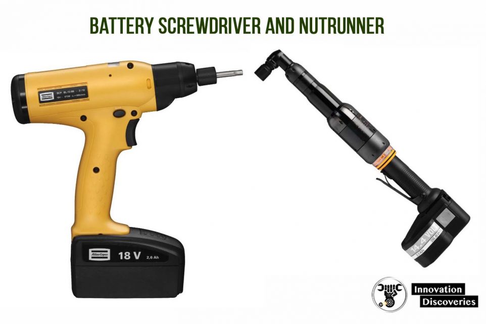
Battery tools
Battery-powered electric screwdrivers and nutrunners have become common tools among craftsmen, carpenters, and do-it-yourself workers where mobility is essential.
Also, during the last few years, the working methods on automotive assembly lines have changed resulting in the increasing use of battery-powered assembly tools.
The advantages are the freedom to move along the assembly line and to work inside closed compartments without air hose interference or the risk of jammed electric cables.
The most advanced battery tools, both in pistol and angle tool configuration, have the same functionality as advanced cabled electric tools.
RECOMMENDATION GUIDE
| Tool | Recommended application |
|---|---|
| Impact wrenches | Loosening and tightening of large dimension bolts during maintenance. High torques with moderate accuracy require- ments. |
| Pulse tools | Assembly ofmachine screws where speed and handiness are important. Medium accuracy. |
| Small screwdrivers | Small screw assembly at low torque and medium to high accuracy. |
| Angle nutrunners | Assembly ofmachine screws and nuts where accuracy require- ments are high. Bolts with limited accessibility. |
| Transducerizednutrunners | Assembly ofmachine screws where in the tightening process the torque and / or angle must be monitored for quality control and certification. |
| Reporting pneumatic tools | Applications where the counting of properly tightened screws in ajoint is essential for product quality control. |
| Electric nutrunners | Assembly where in the tightening process control to a high level of accuracy is necessary. |
| Fixtured spindles | Applications where articulated arms are used to support the reaction torque for multiple spindle tightening and for automatic systems. |
| Battery tools | For maximum mobility and where the air hose or electric cable would limit access or pose asafety risk from ajammed cable. |
Summary
The article reviews the advantages of screw joints for joining components, the characteristics of screw joints, and the influence of the use of different types of tightening tools on the quality of the screw joint.
Different types of tightening tools are presented and their applications are discussed.
The monitoring of the tightening process is explained, and methods for joint quality control in assembly line production are described.
A GUIDE TO TORQUE VALUES
It should be understood that the subject of torque tension loading is beyond the scope of this document.
The information here supplied is an acceptable guide for normal conditions; for critical applications, however, further information and research will be necessary.
In preparing this guide to torque values, the following basic assumptions have been made:
- (a) Bolts and nuts are new, standard finish, uncoated and not lubricated*
- (b) The load will be 90% of the bolt yield strength
- (c) The coefficient of friction (µ) is 0.14
- (d) The final tightening sequence is achieved smoothly and slowly until the torque tool indicates full torque has been obtained.
If lubrication has been applied to the bolt and/or the nut (other than the normal protective oil film), multiply the recommended torque by the appropriate factor shown in the table.
Example: bolt and nut are both phosphates; required torque = torque recommended x 0.75.
| Surface condition of bolt | |||||
| Self | Zinc | Cadmium | Phosphate | ||
| Surface conditionof nut | Self | 1.00 | 1.00 | 0.80 | 0.90 |
| Surface conditionof nut | Zinc | 1.15 | 1.20 | 1.35 | 1.15 |
| Surface conditionof nut | Cadmium | 0.85 | 0.90 | 1.20 | 1.00 |
| Surface conditionof nut | Phosphate and oil | 0.70 | 0.65 | 0.70 | 0.75 |
| Surface conditionof nut | Zinc with wax | 0.60 | 0.55 | 0.65 | 0.55 |
Formula
Accepted formulae relating torque and tension, based on many tests are:
M =PxD / 60
- M = torque lbf.ft
- P = bolt tension lbf
- D = bolt dia.ins
Or for metric sizes:
M = P xD / 5000
- M = torque N.m
- P = bolt tension Newtons
- D = bolt dia. mm
These formulae may be used for bolts outside the range of the tables overleaf.
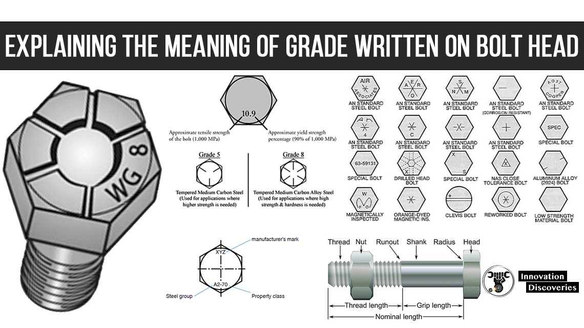
READ: EXPLAINING THE MEANING OF GRADE WRITTEN ON BOLT HEAD
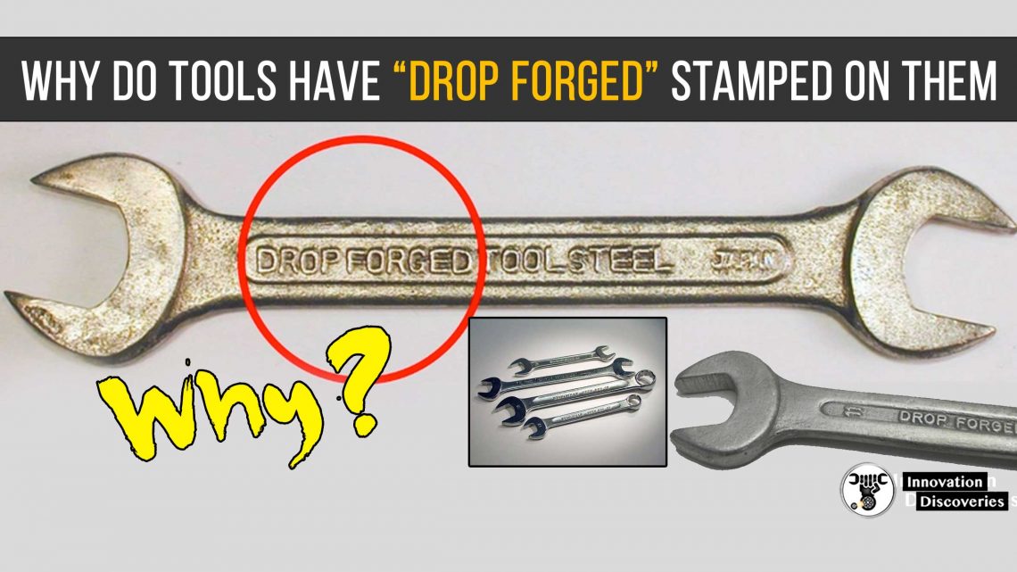
READ: Check Out Why do Tools Have DROP FORGED Stamped On Them
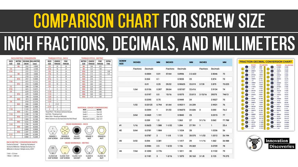
Comparison Chart for Screw Size, Inch Fractions, Decimals, and Millimeters
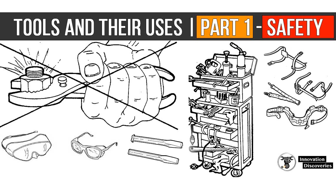
Tools and Their Uses | Part 1 – SAFETY
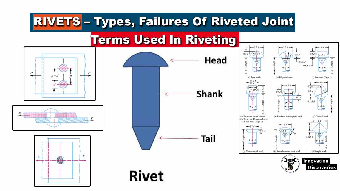
Rivets – Types, Failures Of Riveted Joint, Terms Used In Riveting