After studying this chapter, you will be able to:
- Identify and locate the most important parts of a vehicle.
- Describe the purpose of the fundamental auto- motive systems.
- Explain the interaction of automotive systems.
- Describe major automobile design variations.
- Comprehend later text chapters with a minimum amount of difficulty.
- Correctly answer ASE certification test questions that require a knowledge of the major parts and systems of a vehicle.
The term automobile is derived from the Greek word autos, which means self, and the French word mobile, which means moving.
Today’s “self-moving” vehicles are engineering marvels of safety and dependability.
Over the last century, engineers and skilled workers the world over have used all facets of technology (the application of math, science, physics, and other subjects) to steadily give us a better means of transportation.
You are about to begin your study of the design, construction, service, maintenance, and repair of the modern automobile.
This chapter provides a “quick look” at the major automotive systems.
By knowing a little about each of these systems, you will be better prepared to learn the more detailed information presented later in this text.
Today, the failure of one system can affect the operation of a seemingly unrelated system.
This makes a thorough understanding of how the whole automobile works especially important.
Parts, Assemblies, and Systems
A part is the smallest removable item on a car.
A part is not normally disassembled. The word component is frequently used when referring to an electrical or electronic part.
For example, a spark plug is an ignition system component that ignites the fuel in the engine.
An assembly is a set of fitted parts designed to complete a function.
For example, the engine is an assembly that converts fuel into useable power to move the vehicle.
Technicians must sometimes take assemblies apart and put them back together during maintenance, service, and repair operations.
See Figure 1-1. An automotive system is a group of related parts and assemblies that performs a specific function (job or task).
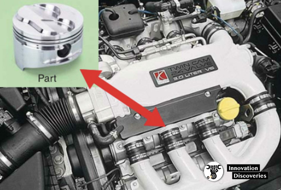
Figure 1-1.
An assembly is a group of parts that work together to perform a function.
For example, an engine is an assembly that contains pistons, which convert the fuel’s heat energy into useable kinetic energy (motion).
As you will learn, an engine has many other parts. (Saturn)
For example, your vehicle’s steering system contains the steering wheel, steering shaft, steering gears, linkage rods, and other parts.
These parts allow you to control the direction of the wheels and tires for maneuvering (turning) your vehicle.
Another example of a familiar system is the brake system.
This system is a group of parts that performs the very important task of slowing and stopping your vehicle quickly and safely.
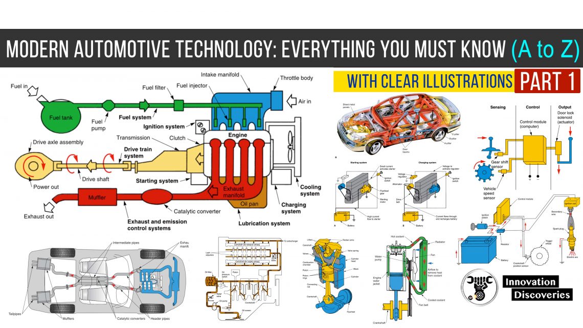
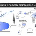
Figure 1-2 shows the major systems of a vehicle. Memorize the name and general location of each system.
Automotive parts and systems can be organized into ten major categories:
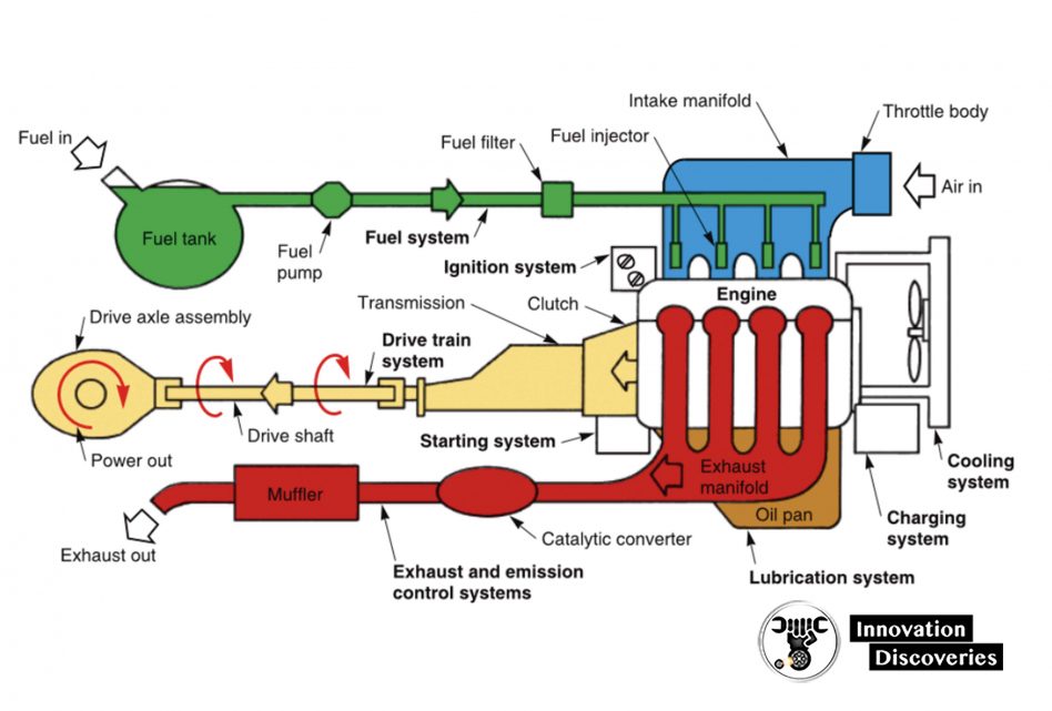
Figure 1-2. Note the general location of the major vehicle systems. Study the flow of fuel, air, exhaust, and power.
- Body and Frame – Support and enclose the vehicle.
- Engine – Provides dependable, efficient power for the vehicle.
- Computer systems – Monitor and control various vehicle systems.
- Fuel system – Provides a combustible air-fuel mixture to power the engine.
- Electrical system – Generates and/or distributes the power needed to operate the vehicle’s electrical and electronic components.
- Cooling and lubrication systems – Prevent engine damage and wear by regulating engine operating temperature and reducing friction between internal engine parts.
- Exhaust and emission control systems – Quiet engine noise and reduce toxic substances emitted by the vehicle.
- Drive train systems – Transfer power from the engine to the drive wheels.
- Suspension, steering, and brake systems – Support and control the vehicle.
- Accessory and safety systems – Increase occupant comfort, safety, security, and convenience.
Frame, Body, and Chassis
The body and frame are the two largest sections of a motor vehicle.
The frame is a strong metal structure that provides a mounting place for the other parts of the vehicle.
The frame holds the engine, transmission, suspension, and other assemblies in position.
The body is steel, aluminum, fiberglass, plastic, or composite skin forming the outside of the vehicle.
The body is painted to give the vehicle an attractive appearance.
The term chassis is often used when referring to a vehicle’s frame and everything mounted to it except the body, tires, wheels, engine, transmission, drive axle assembly, and frame.
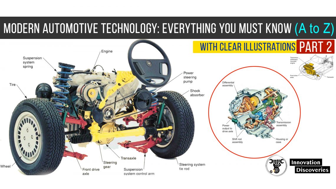
You can see the complex network of automotive parts and systems on the chassis shown in Figure 1-3A.
When each part or system is “disassembled and studied” separately, you will find the inner workings of a motor vehicle easy to understand.
READ:
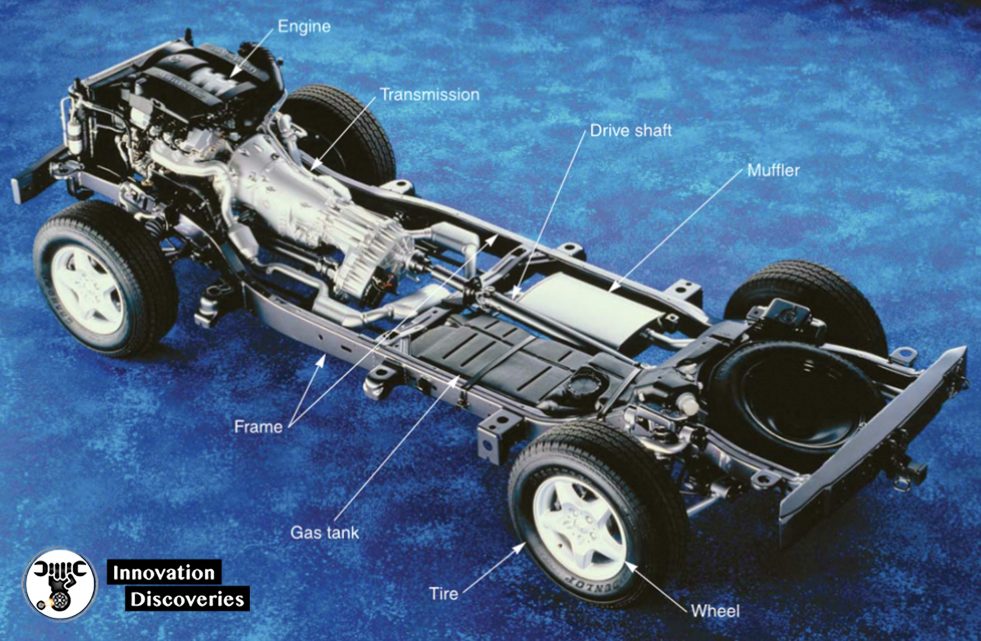
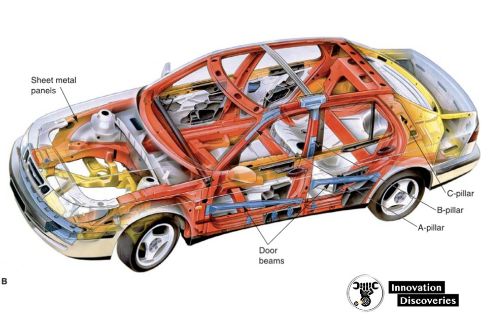
Figure 1-3 – Compare body-over-frame and unibody construction.
A – In body-over-frame construction, the chassis parts bolt to a strong perimeter frame. The body bolts to this thick steel frame.
B – Unibody vehicles do not have a separate perimeter frame. Chassis components bolt directly to the unibody assembly. (DaimlerChrysler, Saab)
In body-over-frame construction, the frame consists of thick steel members.
The chassis parts and the body bolt to this frame.
Also called full-frame construction or perimeter frame construction, this design is heavy but strong.
Body-over-frame construction is used on full-size cars, vans, pickup trucks, and sport-utility vehicles (SUVs).
See Figure 1-3A. With unibody construction, sheet metal body panels are welded together to form the body and frame.
Also called space frame construction or unitized construction, this is the most common type of configuration used to build small and medium passenger cars.
Unibody construction reduces weight, improves fuel economy, and has a high strength-to-weight ratio.
However, unibody vehicles are not as strong as those with body-over-frame construction.
See Figure 1-3B. Body Types Automobiles are available in several body types, including the sedan, hardtop, convertible, hatchback, and station wagon.
In addition, the minivan, the sport-utility vehicle, and the pickup truck have become increasingly popular.
A sedan is a car that has front and back seats and will carry four to six people.
It has center body pillars, or “B” pillars, between the front and rear doors, Figure 1-4A. Both two-door and four-door sedans are available.
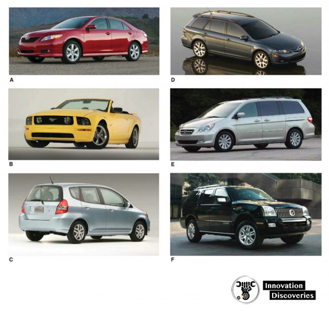
Figure 1-4 – Note the various vehicle body styles.
- A – Sedan.
- B – Convertible.
- C – Hatchback.
- D – Station wagon.
- E – Minivan.
- F – Sport-utility vehicle. (Toyota, Ford, Honda, Mazda)
A hardtop is similar to the sedan, but it has no “B” pillars. Hardtop vehicles are also available in both two- and four-door models.
A convertible has a vinyl or cloth top that can be raised and lowered.
A convertible has no door pillars, and its strength is designed into the frame or floor pan.
Although most convertibles are two-door models, Figure 1-4B, a few four-door convertibles have been produced.
A hatchback, or liftback, has a large rear door for easy access when hauling items.
This style of the car is available in three- and five-door models, Figure 1-4C. A station wagon has a long, straight roof that extends to the rear of the vehicle.
Station wagons have large rear interior compartments and come in two- and four-door models.
Some station wagons have space for up to nine passengers, see Figure 1-4D.
The minivan is similar to the station wagon, but it has a higher roofline for more headroom and cargo space.
Most minivans are designed to carry seven passengers.
See Figure 1-4E. Sport-utility vehicles are often equipped with four-wheel-drive systems and have a tall body design.
They provide the comfort of a passenger car, the interior space of a station wagon, and the durability of a truck, Figure 1-4F.
Common names for various automobile body parts are shown in Figure 1-5.
Note that a vehicle’s right and left sides are denoted as if you were sitting in the car looking forward.
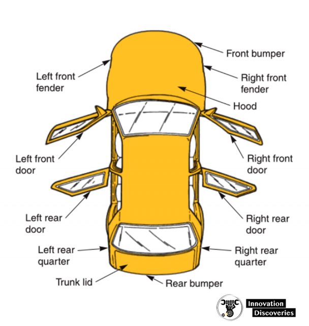
Figure 1-5. The right and left sides of a vehicle are denoted as if you were sitting forward inside the passenger compartment.
Engine
The engine provides the energy to propel (move) the vehicle and operates the other systems.
Most engines consume gasoline or diesel fuel.
The fuel burns in the engine to produce heat. This heat causes gas expansion, creating pressure inside the engine.
The pressure moves internal engine parts to produce power.
See Figure 1-6.
The engine is usually located in the front portion of the body.
Placing the heavy engine in this position makes the vehicle safer in the event of a head-on collision.
In a few vehicles, the engine is mounted in the rear to improve handling.
Refer to Figure 1-7.
READ:
Basic Engine Parts
The basic parts of a simplified one-cylinder engine are shown in Figure 1-8.
Refer to this illustration as each part is introduced.
- The block is metal casting that holds all the other engine parts in place.
- The cylinder is a round hole bored (machined) in the block. It guides piston movement.
- The piston is a cylindrical component that transfers the energy of combustion (burning of air-fuel mixture) to the connecting rod.
- The rings seal the small gap around the sides of the piston.
- They keep combustion pressure and oil from leaking between the piston and the cylinder wall (cylinder surface).
- The connecting rod links the piston to the crankshaft.
- The crankshaft changes the reciprocating (up-and-down) motion of the piston and rod into useful rotary (spinning) motion.
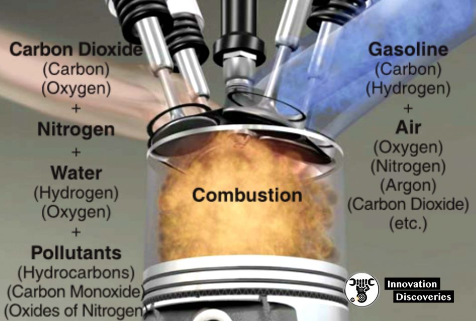
Figure 1-6. | An automotive engine commonly burns gasoline or diesel fuel to produce power. (Ford)
- The cylinder head covers and seals the top of the cylinder. It also holds the valves, rocker arms, and often, the camshaft.
- The combustion chamber is a small cavity (hollow area) between the top of the piston and the bottom of the cylinder head. The burning of the air-fuel mixture occurs in the combustion chamber.
- The valves are open and close to control the flow of the air-fuel mixture into the combustion chamber and the exhaust gases out of the combustion chamber.
- The camshaft controls the opening of the valves.
- The valve springs keep the valves closed when they do not need to be open.
- The rocker arms transfer camshaft action to the valves.
- The lifters, or followers, ride on the camshaft and transfer motion to the other parts of the valve train.
- The flywheel helps keep the crankshaft turning smoothly. It also provides a large gear for the starting motor.
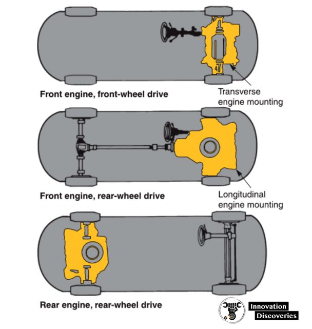
Figure 1-7. The engine can be located in the front or rear of the vehicle. (Dana Corp.)
Four-Stroke Cycle
Automobile engines normally use a four-stroke cycle.
Four separate piston strokes (up or down movements) are needed to produce one cycle (complete series of events).
The piston must slide down, up, down, and up again to complete one cycle.
As the four strokes are described below, study the simple drawings in Figure 1-9.
1. The intake stroke draws the air-fuel mixture into the engine’s combustion chamber.
The piston slides down while the intake valve is open and the exhaust valve is closed.
These pro- duces a vacuum (low-pressure area) in the cylinder.
Atmospheric pressure (outside air pressure) can then force air and fuel into the combustion chamber.
2. The compression stroke prepares the air-fuel mixture for combustion. With both valves closed, the piston slides upward and compresses (squeezes) the trapped air-fuel mixture.
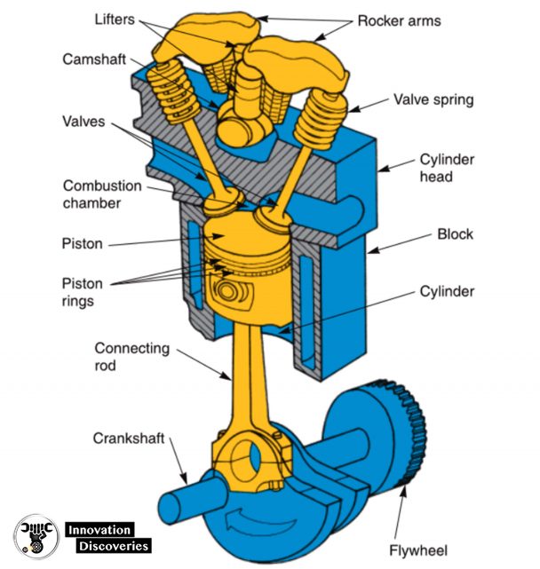
Figure 1-8. Memorize the basic parts of this one-cylinder engine.
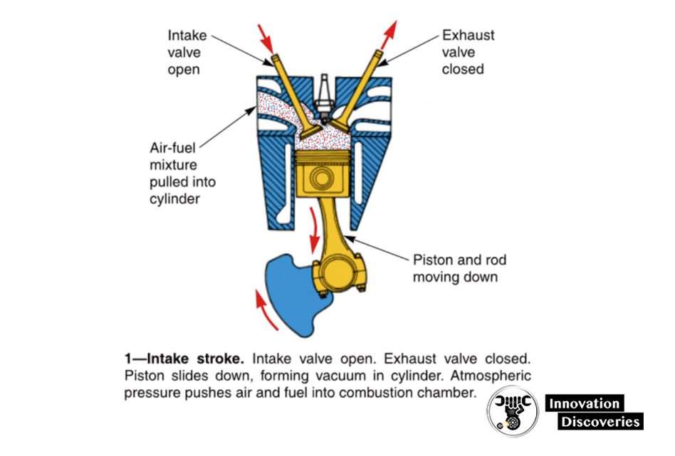
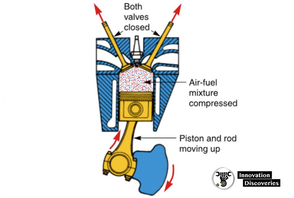
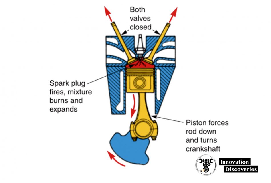
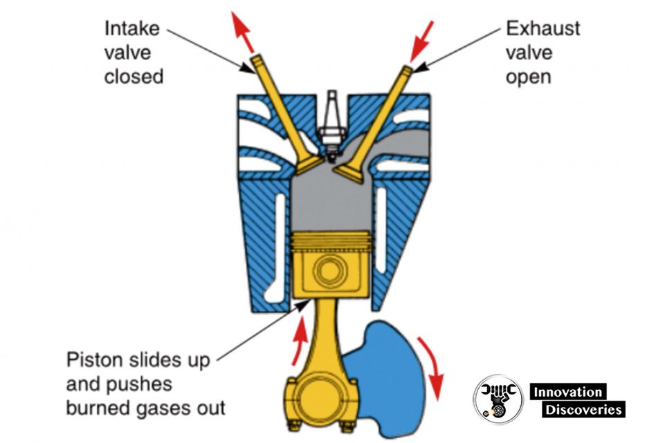
Figure 1-9. A gasoline engine normally operates on a four-stroke cycle. Study the series of events.
3. The power stroke produces the energy to operate the engine. With both valves still closed, the spark plug arcs (sparks) and ignites the compressed air-fuel mixture.
The burning fuel expands and develops pressure in the combustion chamber and on the top of the piston.
This pushes the piston down with enough force to keep the crankshaft spinning until the next power stroke.
4. The exhaust stroke removes the burned gases from the combustion chamber. During this stroke, the piston slides up while the exhaust valve is open and the intake valve is closed.
The burned fuel mixture is pushed out of the engine and into the exhaust system.
During engine operation, these four strokes are repeated over and over. With the help of the heavy fly-wheel, this action produces smooth, rotating power output at the engine crankshaft.
Other devices are needed to lubricate the engine parts, operate the spark plug, cool the engine, and provide the correct fuel mixture.
These devices will be discussed shortly.
Automotive Engines
Unlike the basic one-cylinder engine just discussed, automotive engines are multi-cylinder engines, which means they have more than one piston and cylinder.
Vehicles commonly have 4-, 6-, 8-, or 10-cylinder engines.
The additional cylinders smooth engine operation because there is less time (degrees of crankshaft rotation) between power strokes.
Additional cylinders also increase power output.
An actual automotive engine is pictured in Figure 1-10. Study the shape, location, and relationship of the major parts.
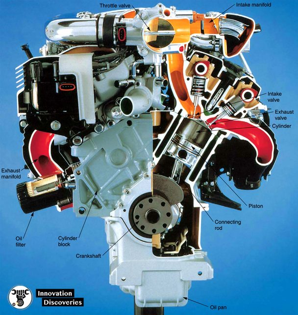
Figure 1-10. Automotive engines are multi-cylinder engines. Locate the major parts and visualize their operation. (Ford)
Computer System
The computer system uses electronic and electrical devices to monitor and control various systems in the vehicle, including the fuel, ignition, drive train, safety, and security systems.
See Figure 1-11.
The use of computer systems has improved vehicle efficiency and dependability.
Additionally, most of these systems have self-diagnostic capabilities.
There are three major parts of an automotive computer system:
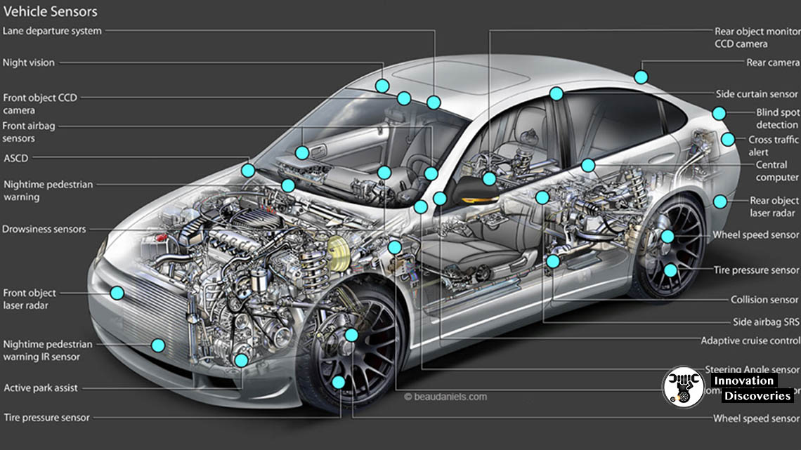
Sensors
Input devices that can produce or modify electrical signals with a change in a condition, such as motion, temperature, pressure, etc.
The sensors are the “eyes, ears, and nose” of the computer system.
READ: VEHICLE SENSORS: FUNCTIONS AND TYPES
Control module
Computer (electronic circuit) that uses signals from input devices (sensors) to control various output devices.
The control module is the “brain” of the computer system.
Actuators
Output devices, such as small electric motors, can move parts when energized by the control module.
The actuators serve as the “hands and arms” of the computer system.
A modern car can have several control modules and dozens of sensors and actuators. These components will be detailed throughout this article.
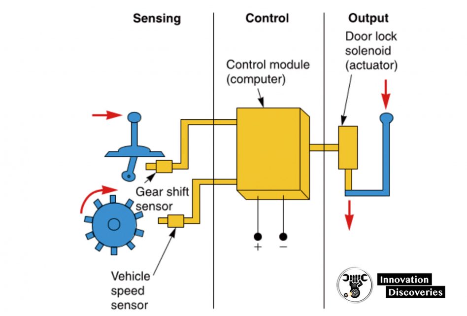
Figure 1-11.
This computer-controlled lock system automatically locks the doors as soon as the vehicle starts moving.
When the gear shift sensor and the vehicle speed sensor send the correct signals to the control module, the module energizes the solenoid (actuator).
The solenoid then converts the electrical signal from the control module to a linear motion, locking the doors.
Fuel System
The fuel system must provide the correct mixture of air and fuel for efficient combustion (burning).
This system must add the right amount of fuel to the air entering the cylinders.
This ensures that a very volatile (burnable) mixture enters the combustion chambers.
The fuel system must also alter the air-fuel ratio (percentage of air and fuel) with changes in operating conditions (engine temperature, speed, load, and other variables).
There are three basic types of automotive fuel systems: gasoline injection systems, diesel injection systems, and carburetor systems.
Look at the three illustrations in Figure 1-12.
More: How Does The Fuel System Work In A Modern Car
Gasoline Injection System
Modern gasoline injection systems use a control module, sensors, and electrically operated fuel injectors (fuel valves) to meter fuel into the engine.
This is the most common type of fuel system on gasoline, or spark ignition, engines.
See Figure 1-12A. An electric fuel pump forces fuel from the fuel tank to the engine.
The control module, reacting to electrical data it receives from the sensors, opens the injectors for the correct amount of time.
Fuel sprays from the open injectors, mixing with the air entering the combustion chambers. A throttle valve controls airflow, engine speed, and engine power.
When the throttle valve is open for more engine power output, the computer holds the injectors open longer, allowing more fuel to spray out.
When the throttle valve is closed, the computer opens the injectors for only a short period, reducing power output.
The throttle valve (air valve) is connected to the accelerator pedal.
When the pedal is pressed, the throttle valve opens to increase engine power output.
Diesel Injection System
A diesel fuel system is primarily a mechanical system that forces diesel fuel (not gasoline) directly into the combustion chambers.
Unlike the gasoline engine, the diesel engine does not use spark plugs to ignite the air-fuel mixture.
Instead, it uses the extremely high.
A – Gasoline injection system.
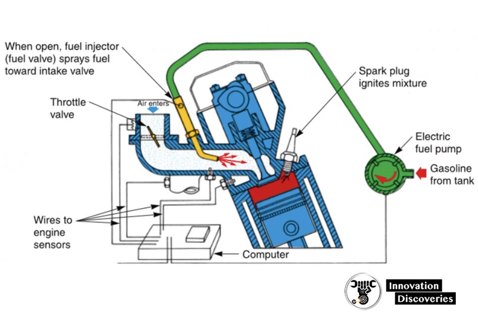
Engine sensors feed information (electrical signals) to a computer about engine conditions.
The computer can then open the injector for the right amount of time. This maintains the correct air-fuel ratio. The spark plug ignites the fuel.
B – Diesel injection system.
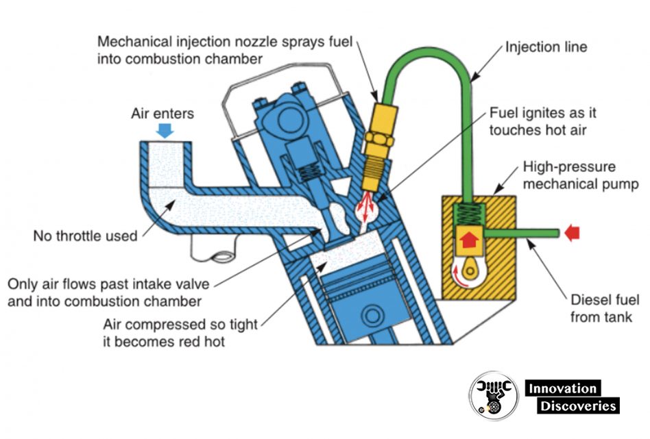
A high-pressure mechanical pump sprays fuel directly into the combustion chamber.
Piston squeezes and heats air enough to ignite the diesel fuel.
Fuel begins to burn as soon as it touches heated air. Note that no throttle valve or spark plug is used.
The amount of fuel injected into the chamber controls diesel engine power and speed.
C- Carburetor fuel system.
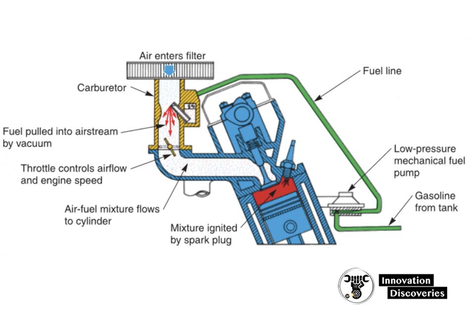
Fuel pump fills carburetor with fuel. When air flows through the carburetor, fuel is pulled into an engine in correct proportions.
The throttle valve controls airflow and engine power output.
Figure 1-12. Note the three basic types of fuel systems. Compare differences.
the pressure produced during the compression stroke to heat the air in the combustion chamber.
The air is squeezed until it is hot enough to ignite the fuel.
Refer to Figure 1-12B. When the mechanical pump sprays the diesel fuel into a combustion chamber, the hot air in the chamber causes the fuel to begin to burn.
The burning fuel expands and forces the piston down on the power stroke.
Electronic devices are commonly used to monitor and help control the operation of today’s diesel injection systems.
Carburetor Fuel System The carburetor fuel system uses engine vacuum (suction) to draw fuel into the engine.
The amount of airflow through the carburetor determines the amount of fuel used. This automatically maintains the correct air-fuel ratio.
Refer to Figure 1-12C. Either a mechanical or an electric fuel pump draws fuel out of the tank and delivers it to the carburetor.
The engine’s intake strokes form a vacuum inside the intake manifold and carburetor.
This causes gasoline to be drawn from the carburetor and into the air entering the engine.
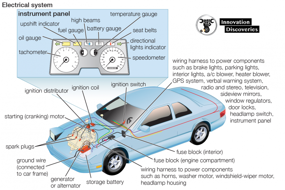
Electrical System
The vehicle’s electrical system consists of several subsystems (smaller circuits): ignition system, starting system, charging system, and lighting system.
Each sub-system is designed to perform a specific function, such as “fire” the spark plugs to ignite the engine’s fuel mixture, rotate the crankshaft to start the engine, illuminate the highway for safe night driving, etc.
READ: How car electrical systems work
Ignition System
An ignition system is needed on gasoline engines to ignite the air-fuel mixture.
It produces an extremely high voltage surge, which operates the spark plugs.
A very hot electric arc jumps across the tip of each spark plug at the correct time.
This causes the air-fuel mixture to burn, expand, and produce power.
Study Figure 1-13. With the ignition switch on and the engine running, the system uses sensors to monitor engine speed and other operating variables.
Sensor signals are fed to the control module.
The control module then modifies and amplifies (increases) these signals into on-off current pulses that trigger the ignition coil.
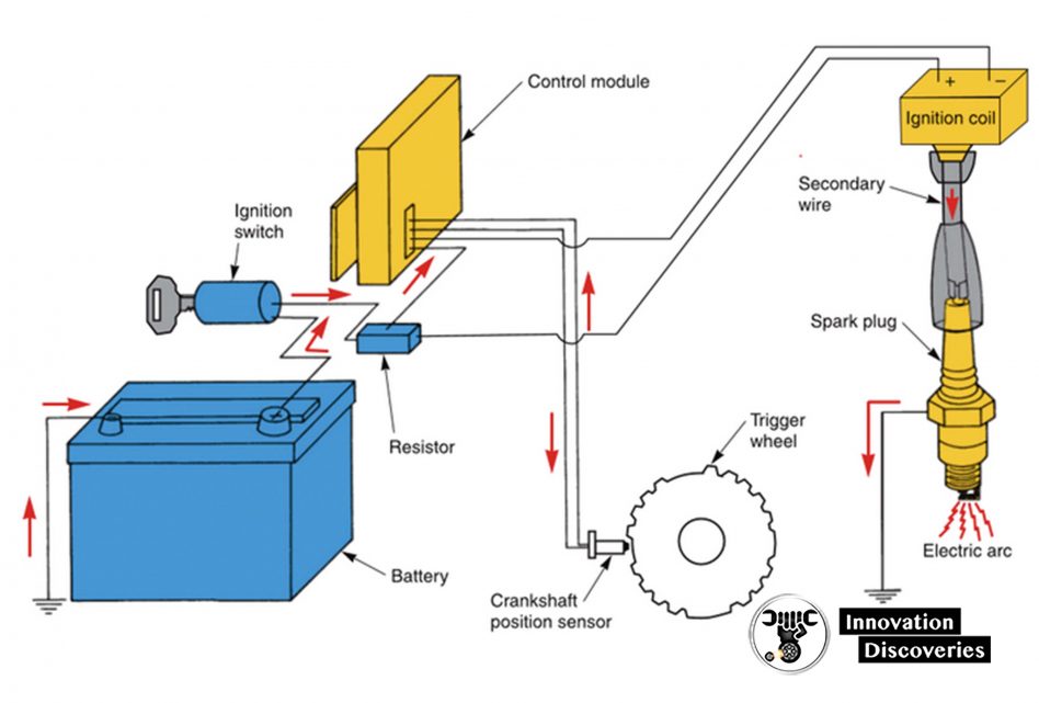
When triggered, the ignition coil produces a high voltage output to “fire” the spark plugs.
When the ignition key is turned off, the coil stops functioning and the spark-ignition engine stops running.
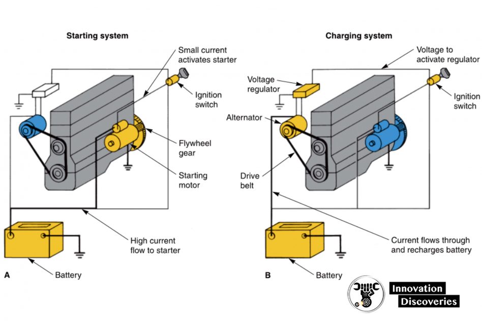
Starting System
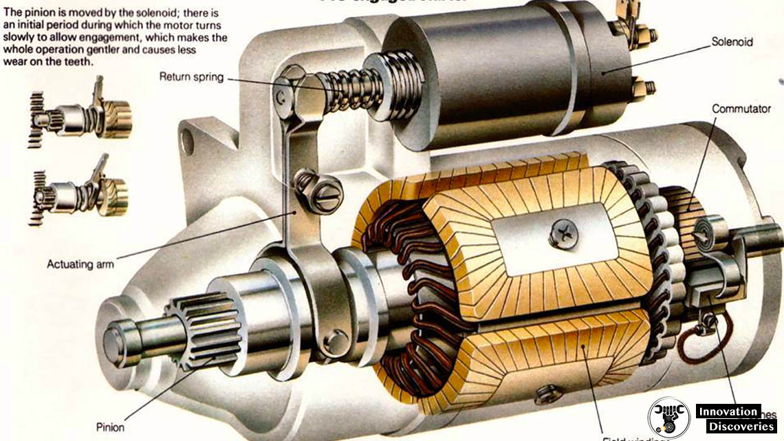
The starting system has a powerful electric starting motor that rotates the engine crankshaft until the engine “fires” and runs on its power.
The major parts of the starting system are shown in Figure 1-14A. A battery provides electricity for the starting system.
When the key is turned to the start position, the current flows through the starting system circuit.
The starting motor is energized, and the starting motor pinion gear engages a gear on the engine flywheel.
This spins the crankshaft. As soon as the engine starts, the driver must shut off the starting system by releasing the ignition key.
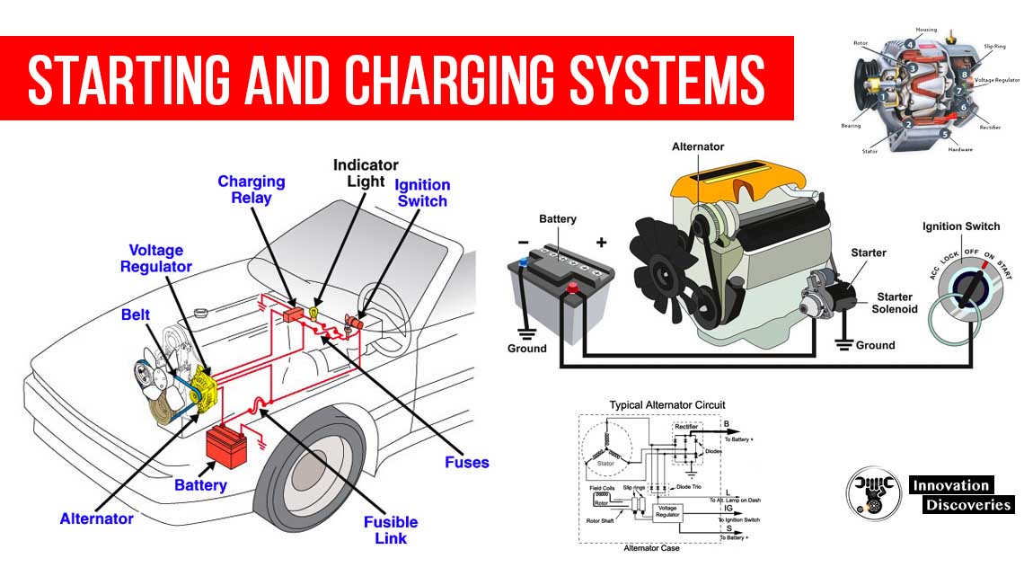
Charging System
The charging system is needed to replace electrical energy drawn from the battery during starting system operation.
To re-energize the battery, the charging system forces electric current back into the battery.
The fundamental parts of the charging system are shown in Figure 1-14B. Study them!
When the engine is running, a drive belt spins the alternator pulley.
The alternator (generator) can then produce electricity to recharge the battery and operate other electrical needs of the vehicle.
A voltage regulator, usually built into the alternator, controls the voltage and current output of the alternator.
Lighting System
The lighting system consists of the components that operate a vehicle’s interior and exterior lights (fuses, wires, switches, relays, etc.).
The exact circuit and part configurations will vary from one model to another.
The exterior lights typically include the headlights, turn signals, brake lights, parking lights, backup lights, and side marker lights.
The interior lights include the dome light, trunk light, instrument panel lights, and other courtesy lights.
Cooling and Lubrication Systems
The cooling and lubrication systems are designed to prevent engine damage and wear.
They are important systems that prevent the engine from self-destructing.
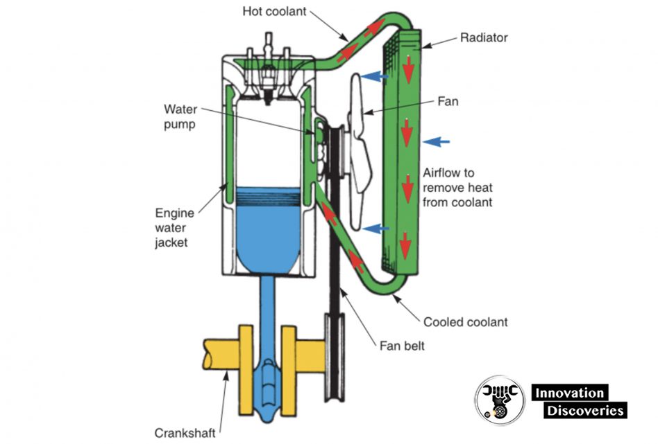
The cooling system maintains a constant engine operating temperature.
It removes excess combustion heat to prevent engine damage and also speeds engine warm-up. Look at Figure 1-15.
The water pump forces coolant (water and antifreeze solution) through the inside of the engine, hoses, and radiator.
The coolant collects heat from the hot engine parts and carries it back to the radiator.
The radiator allows the coolant heat to transfer into the outside air. An engine fan draws cool air through the radiator.
The thermostat controls coolant flow and engine temperature.
It is usually located where the top radiator hose connects to the engine.
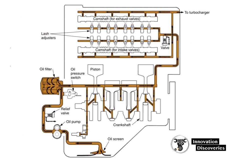
The lubrication system reduces friction and wears between internal engine parts by circulating filtered engine oil to high-friction points in the engine.
The lubrication system also helps cool the engine by carrying heat away from internal engine parts.
Study the parts and operation of the lubrication system shown in Figure 1-16.
Note how the oil pump pulls oil out of the pan and pushes it to various moving parts of the engine.
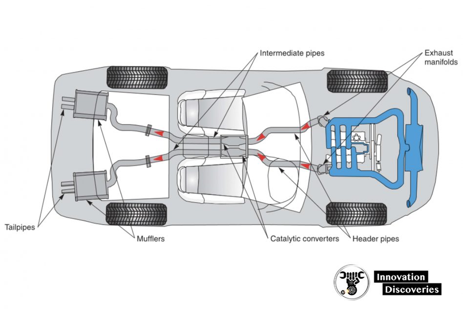
Exhaust and Emission Control Systems
The exhaust system quiets the noise produced during engine operation and routes engine exhaust gases to the rear of the vehicle body.
Figure 1-17 illustrates the basic parts of an exhaust system.
Trace the flow of exhaust gases from the engine exhaust manifold to the tailpipe. Learn the names of the parts.
Various emission control systems are used to reduce the amount of toxic (poisonous) substances produced by an engine.
Some systems prevent fuel vapors from entering the atmosphere (air surrounding the earth).
Other emission control systems remove unburned and partially burned fuel from the engine exhaust.
Later chapters cover these systems in detail.
Drive Train Systems
The drive train transfers turning force from the engine crankshaft to the drive wheels.
Drive train configurations vary, depending on vehicle design.
See Figure 1-18.
The drive train parts commonly found on a front-engine, rear-wheel-drive vehicle include the clutch, transmission, driveshaft, and rear axle assembly.
The drive train parts used on most front-engine, front-wheel-drive vehicles include the clutch, transaxle, and drive axles.
Refer to Figure 1-18 as these components and assemblies are discussed.
Clutch
The clutch allows the driver to engage or disengage the engine and manual transmission or transaxle.
When the clutch pedal is in the released position, the clutch locks the engine flywheel and the transmission input shaft together.
This causes engine power to rotate the transmission gears and other parts of the drive train to propel the vehicle.
When the driver presses the clutch pedal, the clutch disengages power flow and the engine no longer turns the transmission input shaft and gears.
Transmission
The transmission uses various gear combinations, or ratios, to multiply engine speed and torque to accommodate driving conditions.
Low gear ratios allow the vehicle to accelerate quickly.
High gear ratios permit lower engine speed, providing good gas mileage.
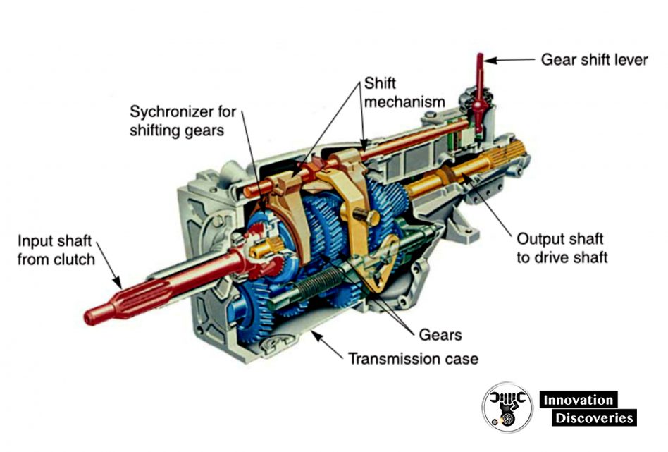
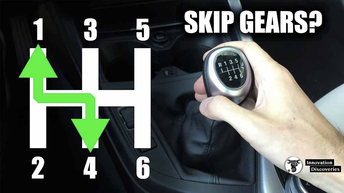
Manual transmission lets the driver change gear ratios to better accommodate driving conditions, Figure 1-19.
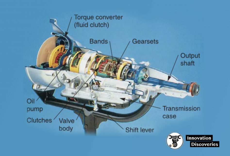
An automatic transmission, on the other hand, does not have to be shifted by the driver.
It uses an internal hydraulic system and, in most cases, electronic controls to shift gears.
The input shaft of an automatic transmission is connected to the engine crankshaft through a torque converter (fluid coupling) instead of a clutch.
The elementary parts of an automatic transmission are pictured in Figure 1-20.
Drive Shaft
The driveshaft, or propeller shaft, transfers power from the transmission to the rear axle assembly.
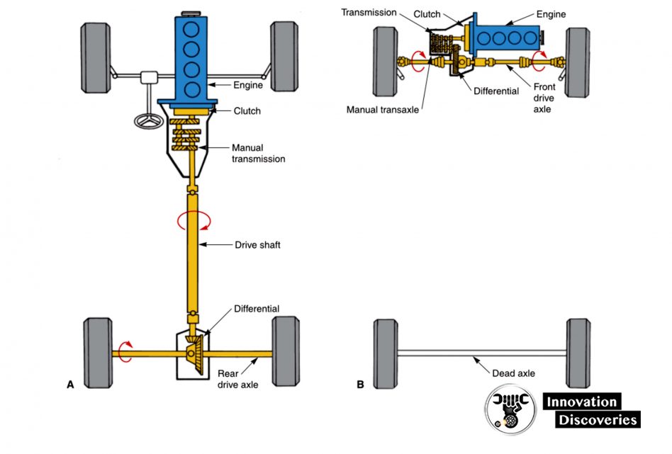
- A – Front-engine, rear-wheel-drive vehicle.
- B – Front-engine, front-wheel-drive vehicle.
Stay tuned for the rest of the article tomorrow…
3 Comments