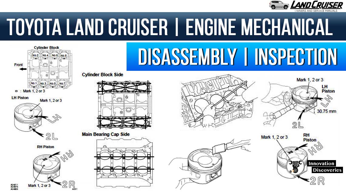
1. CLEAN CYLINDER BLOCK
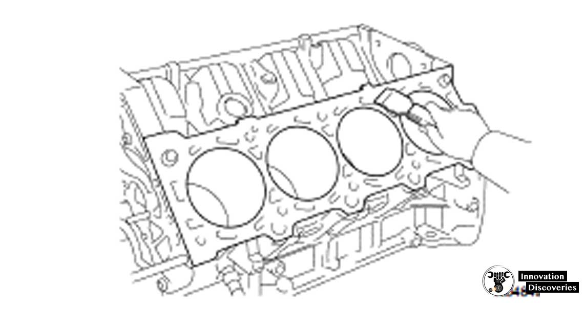
(a) Using a gasket scraper, remove all the gasket material from the top surface of the cylinder block.
(b) Using a soft brush and solvent, thoroughly clean the cylinder block.
Read More: WHAT IS AN ENGINE BLOCK?
Also, Read:
2. INSPECT CYLINDER BLOCK
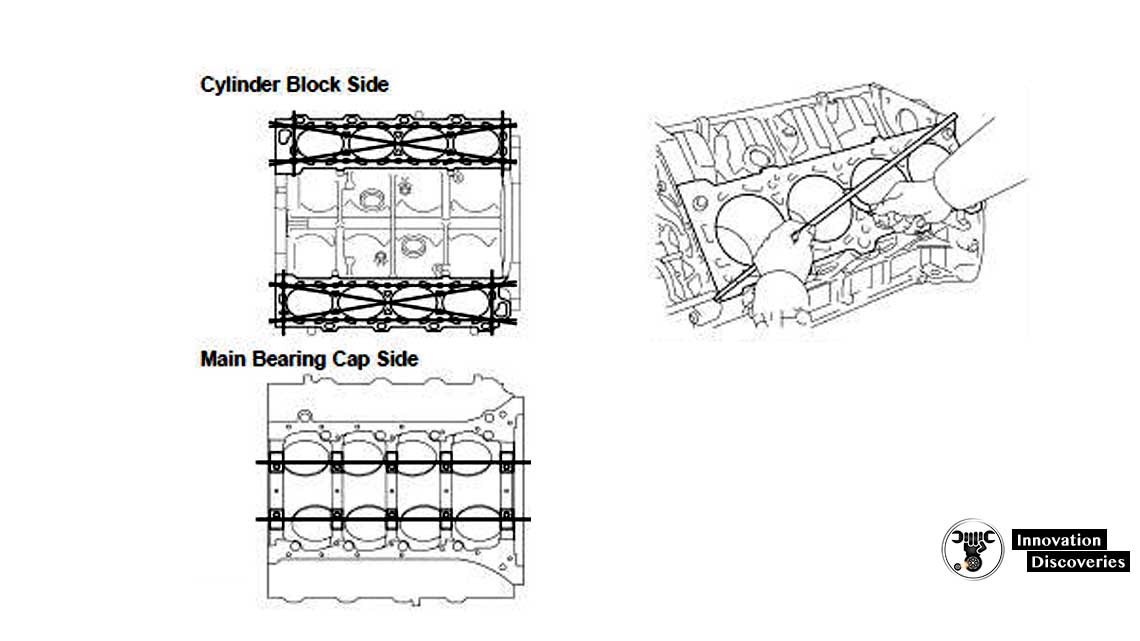
(a) Inspect for flatness.
Using a precision straight edge and a feeler gauge, measure the surfaces contacting the cylinder head and main bearing cap for a warp.
Maximum warpage: 0.07 mm (0.0028 in.)
If the warp is greater than the maximum, replace the cylinder block.
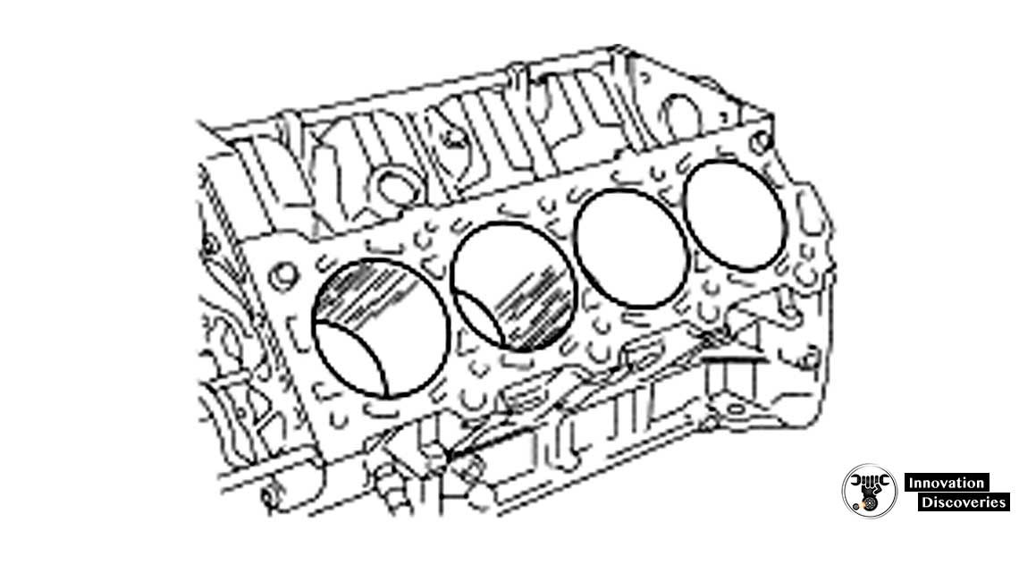
(b) Visually check the cylinder for vertical scratches.
If deep scratches are found, rebore all the 8 cylinders and replace all the 8 pistons ( EM-104 ).
If necessary, replace the cylinder block.
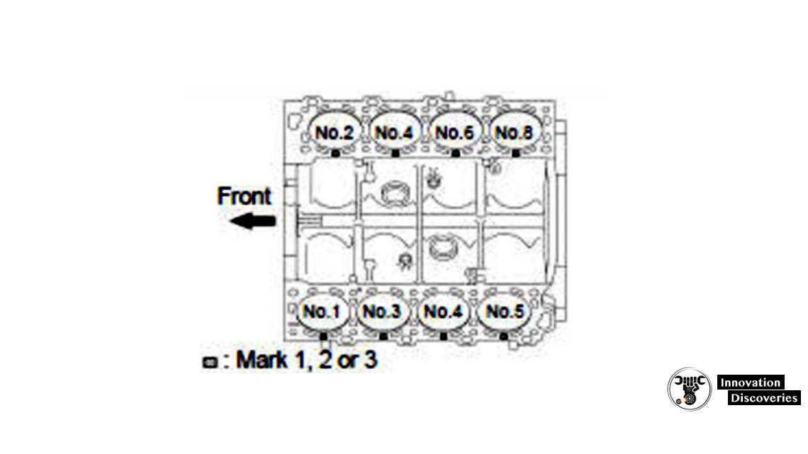
c) Inspect the cylinder bore diameter.
HINT: There are 3 sizes of the standard cylinder bore diameter, marked “1”, “2” and “3” accordingly. The mark is stamped on the top of the cylinder block.
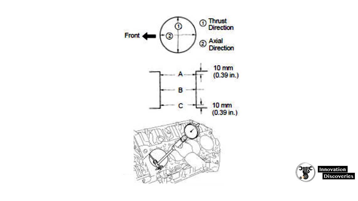
Using a cylinder gauge, measure the cylinder bore diameter at positions A, B and C in the thrust and axial directions.
READ MORE:
Standard diameter:
Maximum diameter: 94.23 mm (3.7098 in.)
If the diameter is greater than the maximum, rebore all the 8 cylinders and replace all the 8 pistons ( EM-104 ).
If necessary, replace the cylinder block.
(d) Remove the cylinder ridge.
If the wear is less than 0.2 mm (0.008 in.), using a ridge reamer, grind the top of the cylinder.
e) Using vernier callipers, measure the thread outside diameter of the main bearing cap bolt.
Standard diameter: 10.760 – 10.970 mm (0.4236 – 0.4319 in.) Minimum diameter: 10.40 mm (0.4094 in.)
If the diameter is less than the minimum, replace the cap bolt.
3. CLEAN PISTON
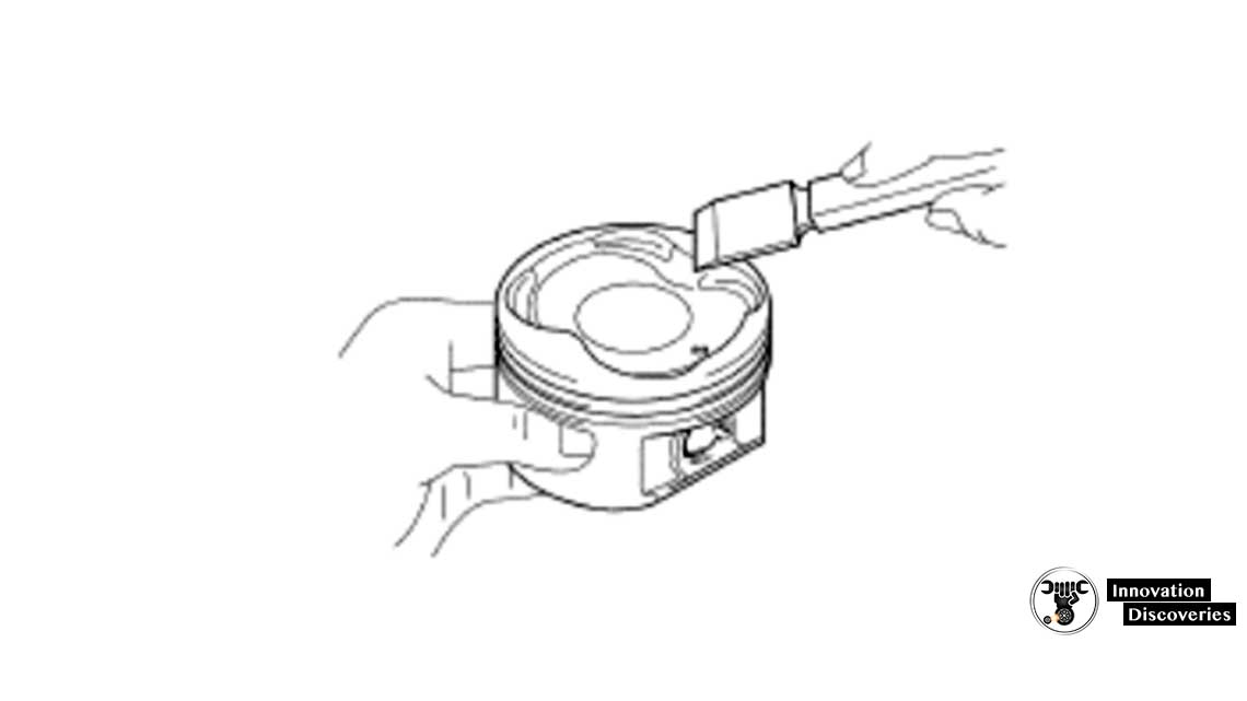
(a) Using a gasket scraper, remove the carbon from the piston top.
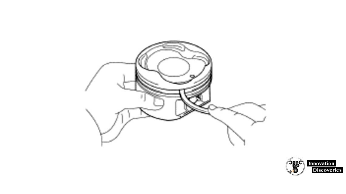
(b) Using a groove cleaning tool or broken ring, clean the piston ring grooves.
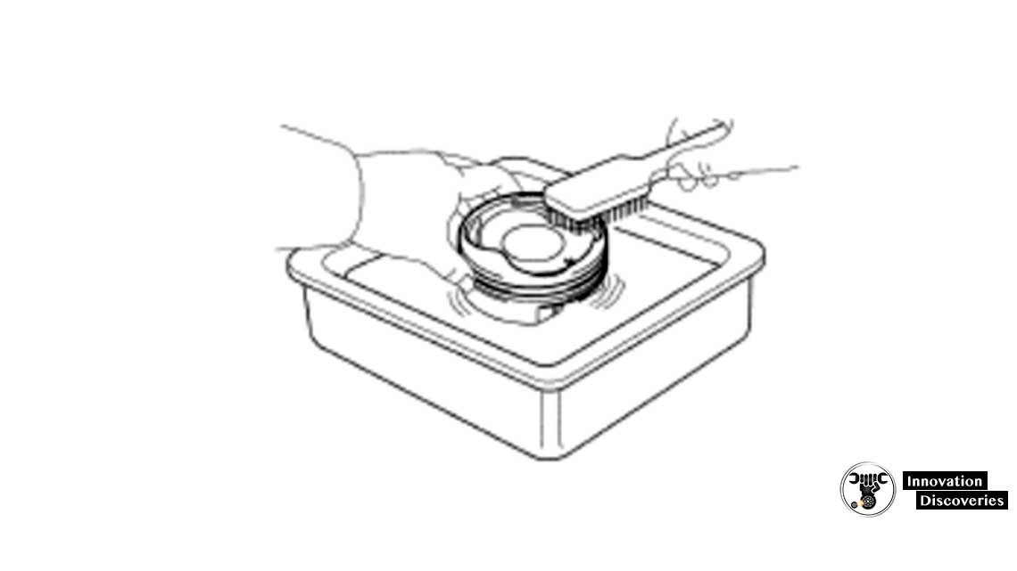
(c) Using solvent and a brush, thoroughly clean the piston.
NOTICE: Do not use a wire brush.
4. INSPECT PISTON AND CONNECTING ROD
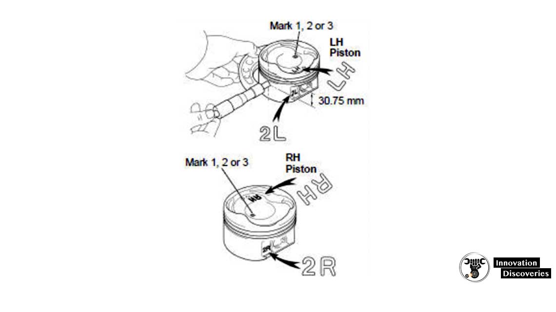
(a) Inspect the piston oil clearance.
HINT: There are 3 sizes of the standard piston diameter, marked “1”, “2” and “3” accordingly. The mark is stamped on the piston top.
- Using a micrometer, measure the piston diameter at right angles to the piston pin center line, 30.75 mm (1.2106 in.) from the piston head.
Piston diameter:
- Measure the cylinder bore diameter in the thrust directions. (See step 2 above)
- Subtract the piston diameter from the cylinder bore diameter.
Standard oil clearance: 0.090 – 0.111 mm (0.0035 – 0.0044 in.) Maximum oil clearance: 0.13 mm (0.0051 in.)
If the oil clearance is greater than the maximum, replace all the 8 pistons and rebore all the 8 cylinders.
( EM-104 ) If necessary, replace the cylinder block.
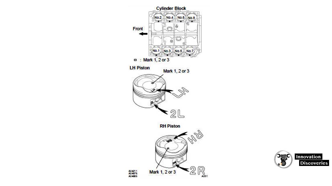
HINT Use new cylinder block:
- Use a piston with the same number mark as the cylinder diameter marked on the cylinder block.
- The shape of the piston varies for the LH and the RH banks. The LH piston is marked as “LH” and “2L”, and the RH piston as “RH” and “2R”.
(b) Inspect the piston ring groove clearance.
Using a feeler gauge, measure the clearance between a new piston ring and the wall of the ring groove.
Ring groove clearance:
If the clearance is not as specified, replace the piston.
(c) Inspect the piston ring end gap.
- Insert the piston ring into the cylinder bore.
- Using a piston, push the piston ring to a little beyond the bottom of the ring travel, 105 mm (4.13 in.) from the top of the cylinder block.
- Using a feeler gauge, measure the end gap.
Standard end gap:
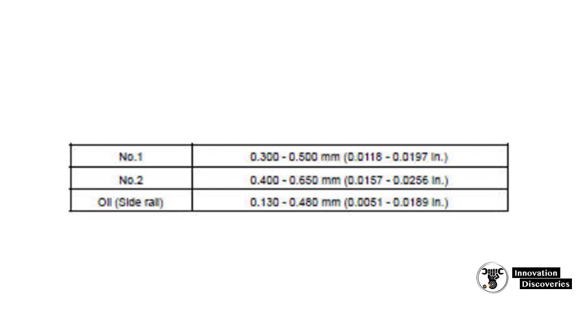
Maximum end gap:
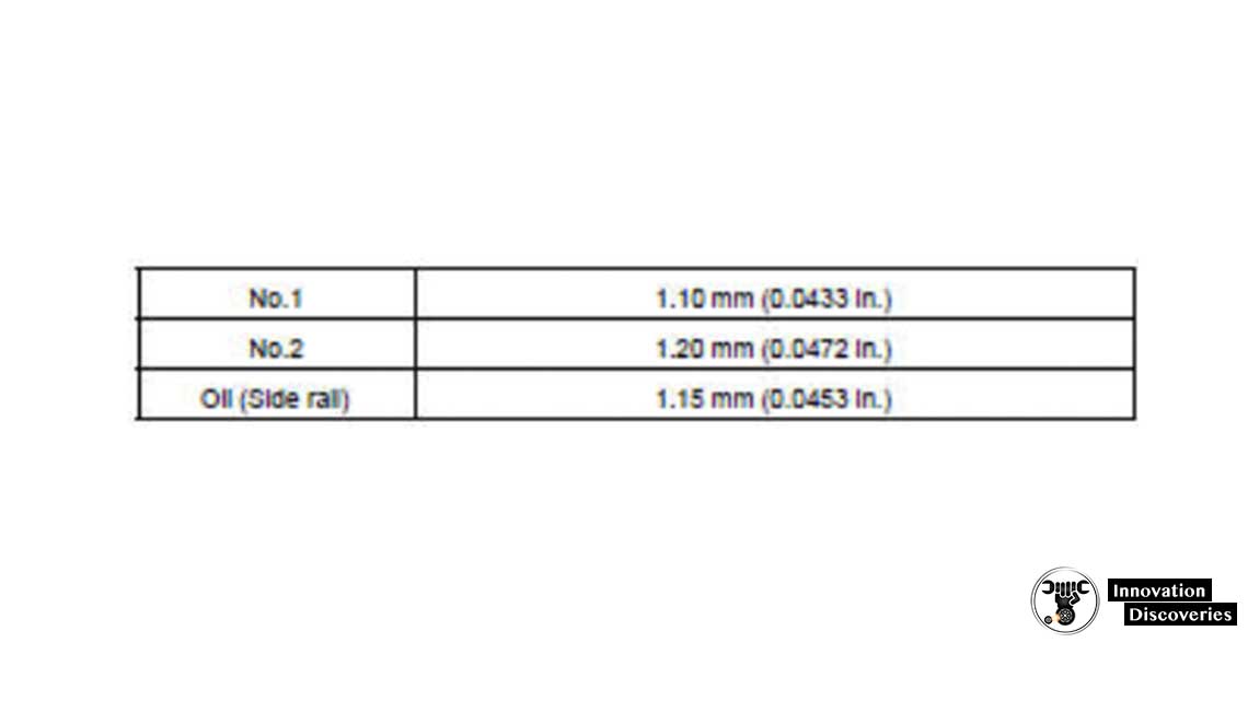
If the end gap is greater than the maximum, replace the piston ring.
If the end gap is greater than the maximum, even with a new piston ring, rebore all the 8 cylinders ( EM-104 ) or replace the cylinder block.
(d) Inspect the piston pin fit.
At 60C (140F), you should be able to push the piston pin into the piston pin hole with your thumb.
(e) Using a rod aligner and the feeler gauge, check the connecting rod alignment.
- Check for a bend.
Maximum bend: 0.05 mm (0.0020 in.) per 100 mm (3.94 in.)
If the bend is greater than the maximum, replace the connecting rod assembly.
- Check for twist
Maximum twist: 0.15 mm (0.0059 in.) per 100 mm (3.94 in.)
If the twist is greater than the maximum, replace the connecting rod assembly
(f) Inspect the piston pin oil clearance.
- Using a calliper gauge, measure the inside diameter of the connecting rod bushing.
Bushing inside diameter: 22.005 – 22.014 mm (0.8663 – 0.8667 in.)
- Using a micrometer, measure the piston pin diameter.
Piston pin diameter: 21.997 – 22.009 mm (0.8660 – 0.8664 in.)
- Subtract the piston pin diameter from the bushing inside diameter.
Standard oil clearance: 0.005 – 0.011 mm (0.0002 – 0.0004 in.) Maximum oil clearance: 0.05 mm (0.0020 in.)
If the oil clearance is greater than the maximum, replace the bushing. If necessary, replace the piston and the piston pin as a set.
(g) Using vernier callipers, measure the tension portion of the connecting rod bolt.
Standard diameter: 7.200 – 7.300 mm (0.2835 – 0.2874 in.) Minimum diameter: 7.00 mm (0.2756 in.)
If the diameter is less than the minimum, replace the bolt.
READ MORE:
6 MOST COMMON CRANKSHAFT POSITION SENSOR SYMPTOMS
5. INSPECT CRANKSHAFT
(a) Inspect for circle runout.
- Place the crankshaft on V-blocks.
- Using a dial indicator, measure the circle runout at the center journal.
Maximum circle runout: 0.08 mm (0.0031 in.)
If the circle runout is greater than the maximum, replace the crankshaft.
(b) Inspect the main journals and the crankpins.
- Using a micrometer, measure the diameter of each main journal and crankpin
Main journal diameter: 66.988 – 67.000 mm (2.6373 – 2.6378 in.)
Crankpin diameter: 51.982 – 52.000 mm (2.0465 – 2.0472 in.)
If the diameter is not as specified, check the oil clearance ( EM-88 ). If necessary, replace the crankshaft.
- Check each main journal and crankpin for taper and out-of-round as shown.
Maximum taper and out-of-round: 0.02 mm (0.0008 in.)
If the taper and out-of-round are greater than the maximum, replace the crankshaft.
Download: 1996 Toyota Land Cruiser Electrical Wiring Diagram
Visit Forum
Visit Our Friendly Website



One Comment