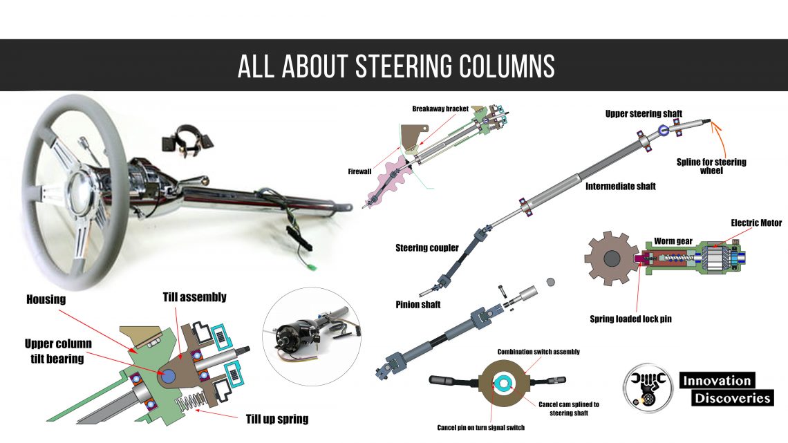
Steering column components
- Steering wheel
- Airbag
- Clock Spring
- Steering lock plate
- Steering angle sensor
- Cancel cam
- Lock cylinder
- Ignition switch
- Turn signal switch
- Headlight switch
- Wiper washer switch
- Cruise control switch
- Upper steering shaft
- Lower steering shaft
- Shaft bearings
- Tilt housing
- Constant velocity joint
- Steering coupler
Steering columns and crash
- The modern steering column is the result of thousands of crash tests.
- The information learned from each test has helped thousands of people survive accidents that would have been fatal in older vehicles.
- In a crash, the steering has to be capable of collapsing from both ends.
- This prevents the steering column and shaft from impaling the driver’s chest and helps to absorb the kinetic energy of the driver’s body.
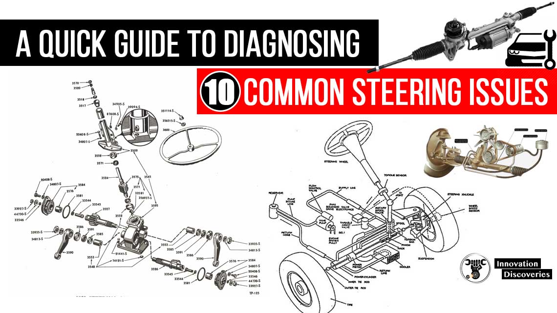
Steering shafts and couplings
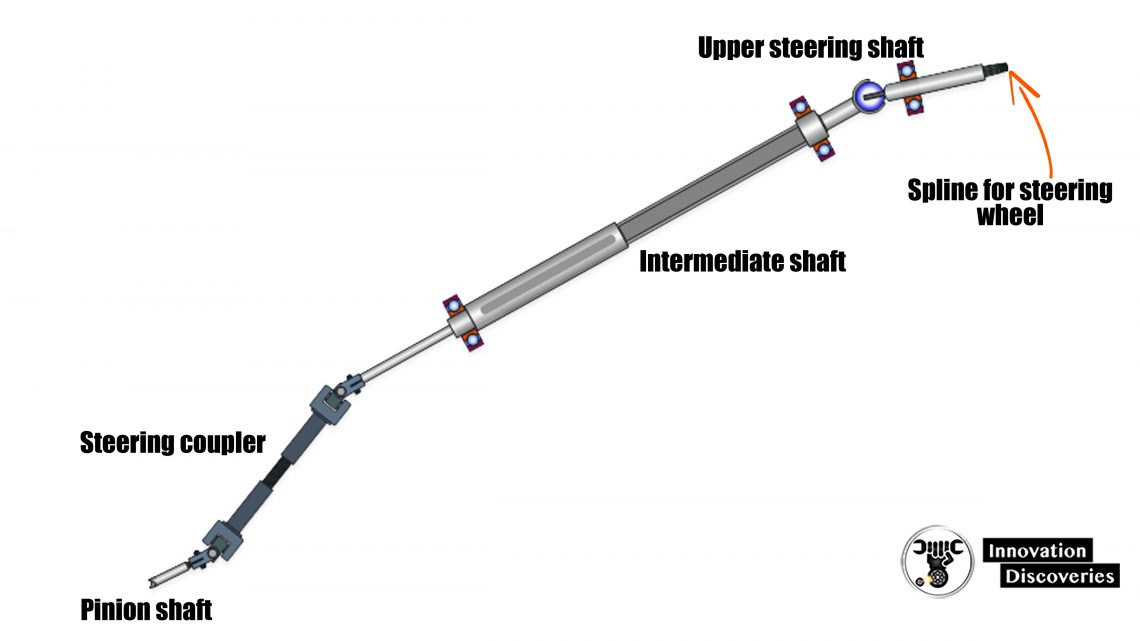
The connection between the steering wheel and pinion shaft/worm shaft is normally in three parts.
- Upper steering shaft
- Intermediate steering shaft
- Steering coupler
Steering wheel
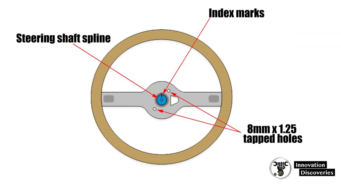
- The steering wheel is connected to the upper steering shaft via a tapered spline.
- Once the steering wheel retaining nut has been torqued the steering wheel can only be removed from the steering shaft by a steering wheel puller.
- Two threaded holes on either side of the spline are provided for the puller tool.
- ( Index marks Steering shaft spline 8mm x 1.25 tapped holes )
- A pass-through hole in the hub allows the electrical connector for the airbag, horn switch, and steering wheel-mounted switches to connect to the clock spring.
Steering shaft constant velocity joint
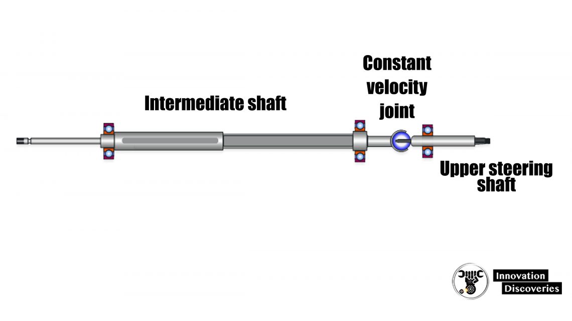
- Nearly all modern cars have to tilt wheel-type steering columns.
- A constant velocity type joint is needed to allow the steering effort to pass through a 0o to 20o angle without the steering being jerky.
- The constant velocity joint connects the upper shaft to the intermediate shaft.
Intermediate shaft
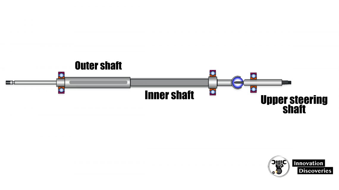
- The intermediate shaft is collapsible.
- ( Outer shaft Upper steering shaft Inner shaft The intermediate shaft is collapsible. )
- The outer shaft is hollow allowing the solid inner shaft to telescope into the outer shaft tube.
- Whenever working on a steering column you must be careful to not tap on the ends of the shafts or exert any pressure that might shorten the assembly.
Shaft support bearings
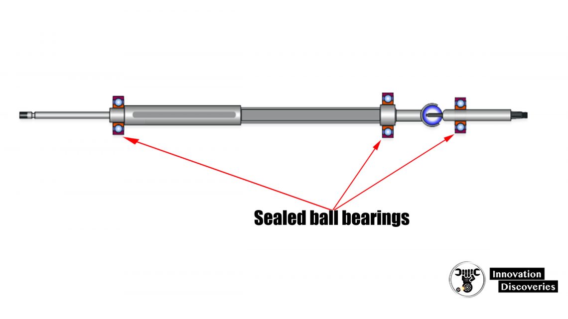
- The intermediate shaft and the upper shaft are supported by sealed ball bearings.
Steering Coupler
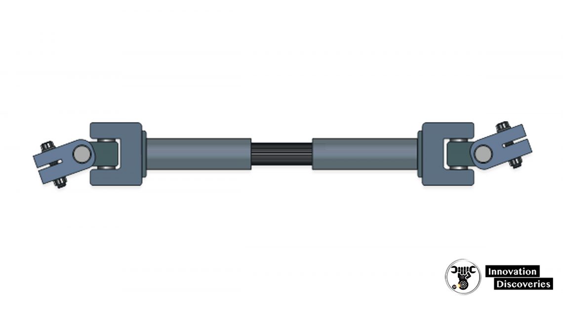
- The coupler connects the intermediate shaft to the pinion shaft or worm shaft.
- Like the intermediate shaft, the coupler also telescopes.
- This allows the sub-frame and rack to move on their rubber mounts without passing shock and vibration into the intermediate shaft.
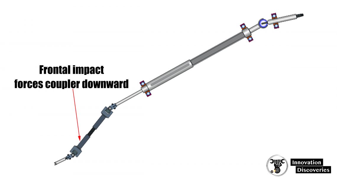
- The steering coupler is normally located on the engine compartment side of the firewall.
- The coupler is mounted at an angle relative to the steering column so that in a severe frontal impact the sub-frame and rack will be pushed downward and under the firewall.
Pinch bolt joints
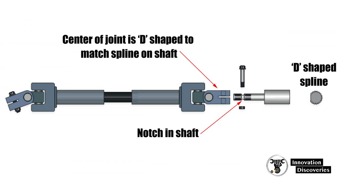
- Steering couplers are normally attached to shafts via a pinch bolt joint.
- The joint and shaft are connected by ‘D’ shaped splines.
- The pinch bolt passes through the notch in the shaft as a safety mechanism – if the bolt loosens the joint will not separate from the shaft.
Outer column
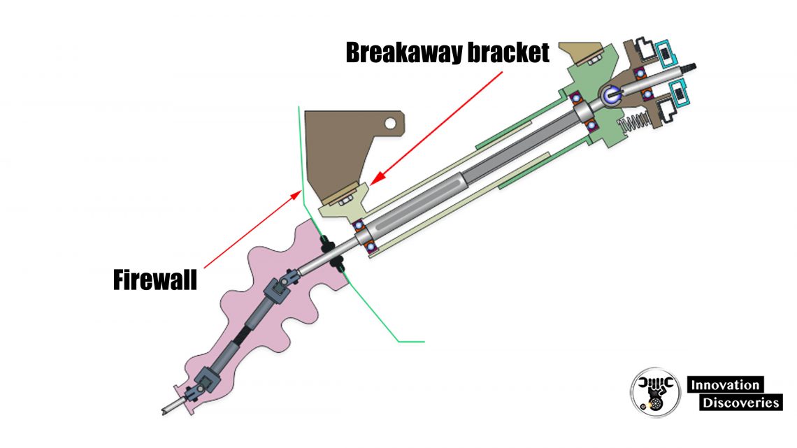
- The shafts and bearings are supported by collapsible steel housing.
- The housing connects to brackets on the body that can break away and slide inward in a crash.
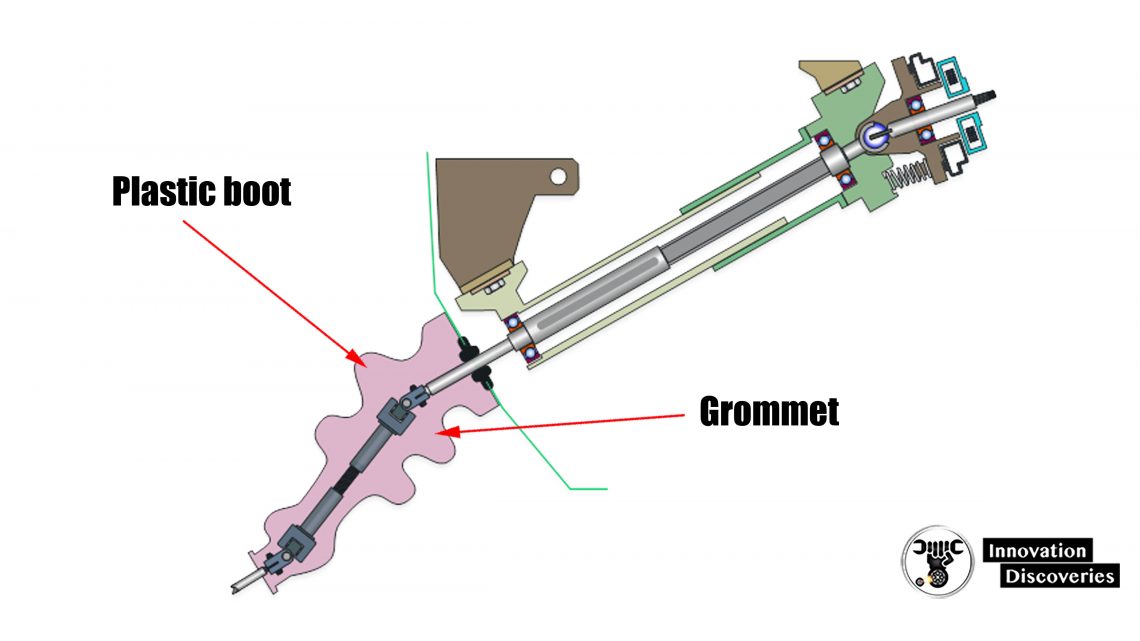
- A rubber grommet mounted in the firewall prevents dirt and water from entering the passenger compartment
- A plastic boot located between the steering rack and firewall helps to keep dirt and water away from the grommet.
Upper column
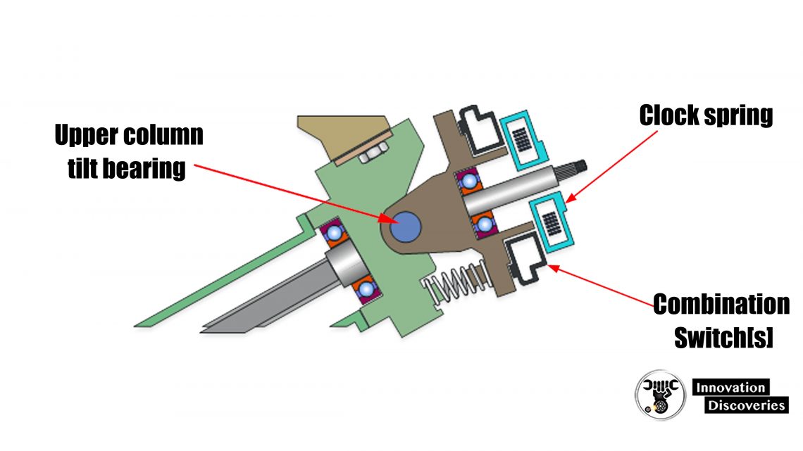
- The clock spring connects the airbag, horn and electrical switches mounted on the steering wheel cover to the vehicle’s electrical system.
- It is mounted to the tilt assembly directly below the steering wheel.
Clock Spring
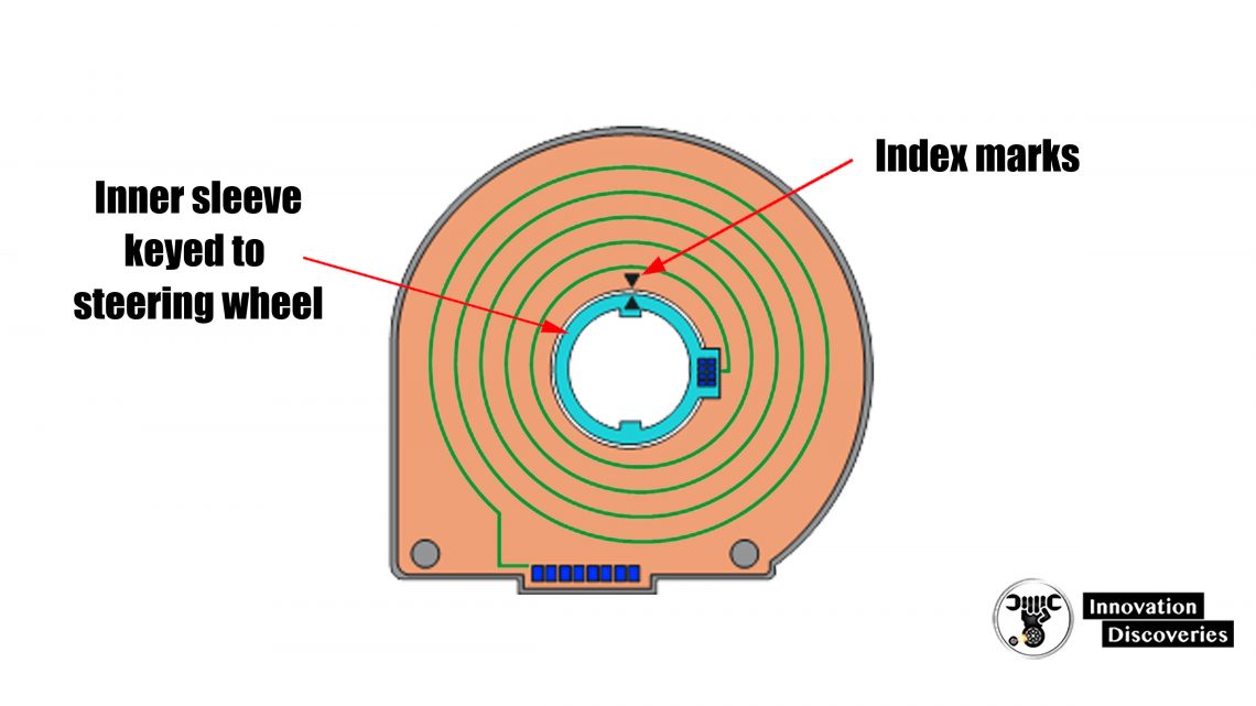
- The clock spring is a spool of the ribbon cable that winds and unwinds as the steering wheel is turned.
- Most clock springs can turn about 4 to 5 turns from fully unwound to wound.
- To prevent damage to the clock spring it must be centered and removed whenever the steering gear is serviced.
- To the center, the clock spring turns the wheels straight ahead with the steering wheel at 12 o’clock.
Upper column
- The combination switch assembly is mounted to the outer face of the tilting assembly.
- The combination switch is operated by the stalks on the outside of the steering column.
- Some manufacturers integrated all the switches into one assembly.
- Otherwise, there are two switches on either side.
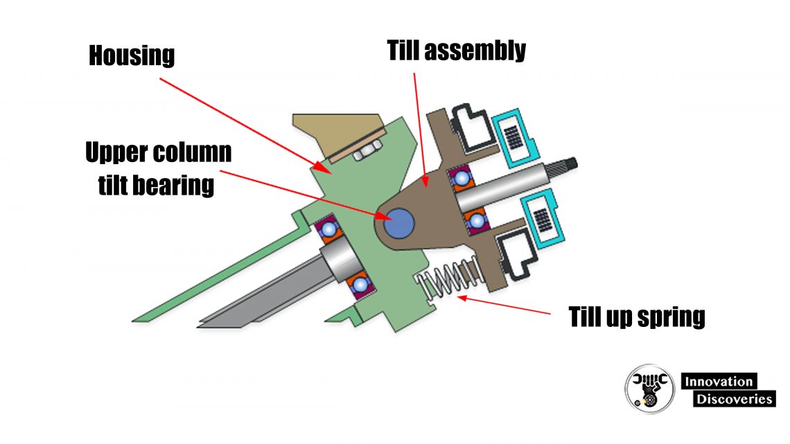
- The tilt mechanism is spring-loaded so that the steering wheel will rise if the lock lever is released by accident.
- The lock lever clamps the sides of the tilt assembly to the housing.
Plate type steering lock
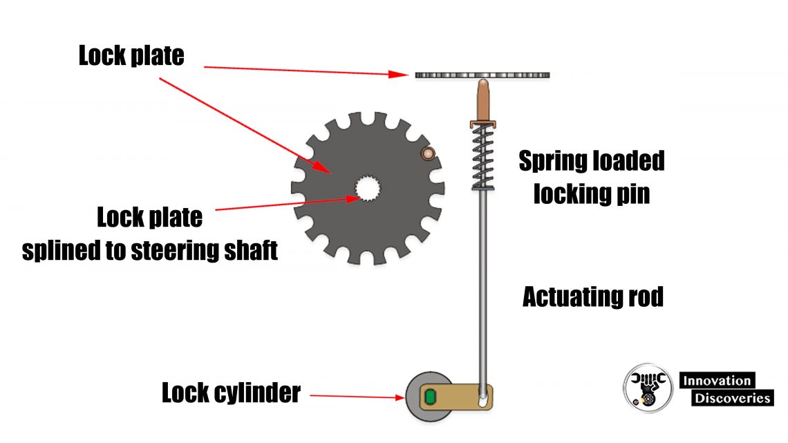
- The steering lock plate is a stamped steel plate that is splined to the steering shaft.
- When the ignition key is turned to the lock position the actuating rod pushes a spring-loaded locking pint into a notch in the lock plate.
Pawl type steering lock
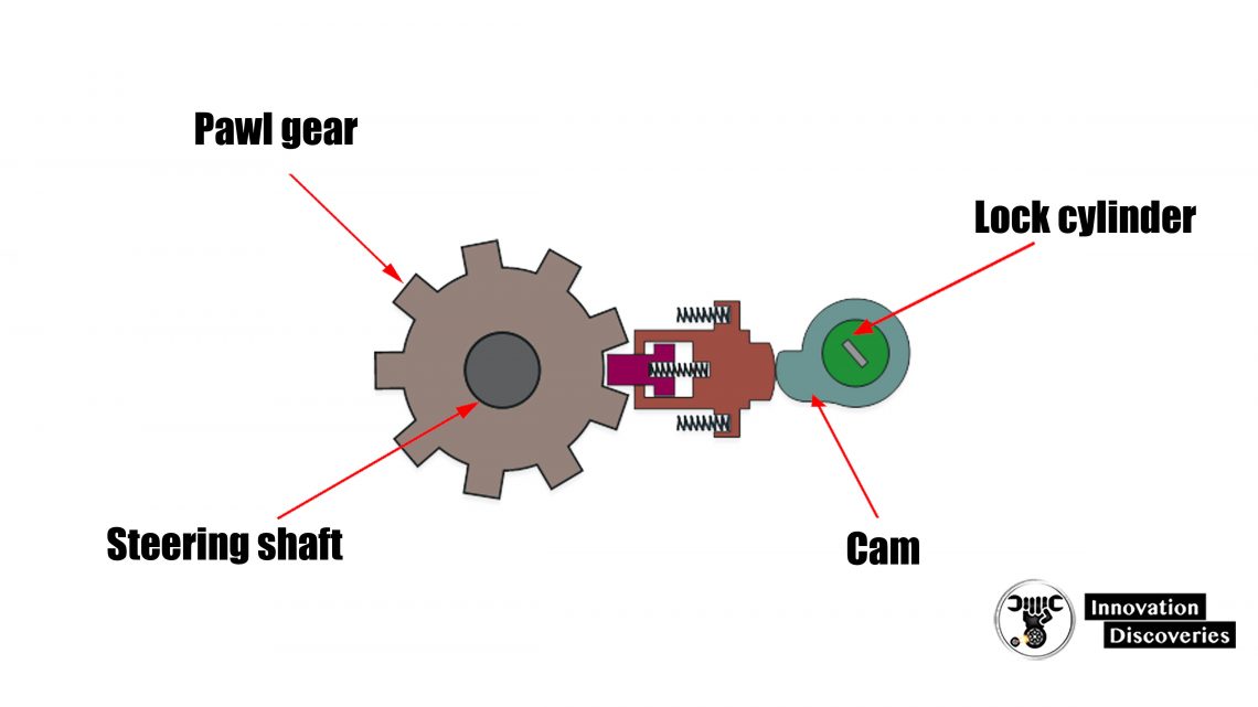
- In this type of lock mechanism, a pawl gear is machined directly on the intermediate steering shaft.
- The locking pin is actuated directly off of a cam on the back of the lock cylinder.
Read: SUSPENSION INSPECTION – QUESTIONS AND ANSWERS
Steering locks for keyless ignition
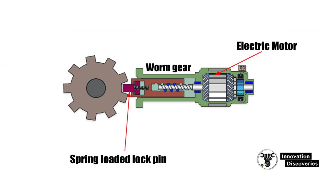
- Keyless ignition systems use a radio transmitter to actuate the door locks and ignition system and do not have a conventional lock cylinder on the steering column.
- To lock the steering system a small electric motor moves the locking pin into and out of the pawl gear when commanded by the BCM or security system control module.
Lock cylinder
- Mechanical lock cylinders are mounted to the lower section [stationary] of the steering column housing.
- The lock cylinder is retained in its bore in the housing by a spring-loaded pin.
- Inserting a pin punch into a small hole in the housing will depress the lock pin so that the entire lock cylinder can be removed.
- The lock cylinder must be in the accessory position to allow the pin to be depressed.
Ignition switch
- Ignition switches are actuated directly by the lock cylinder or remotely by an actuating rod.
- Most modern cars have a direct-acting ignition switch bolted to the lock cylinder housing.
- Remote ignition switches are located on the base of the steering column housing and are actuated by a rod that connects to the lock cylinder at the top of the column.
- Remote ignition switches have slotted screw holes that allow the switch to be adjusted.
Turn signal
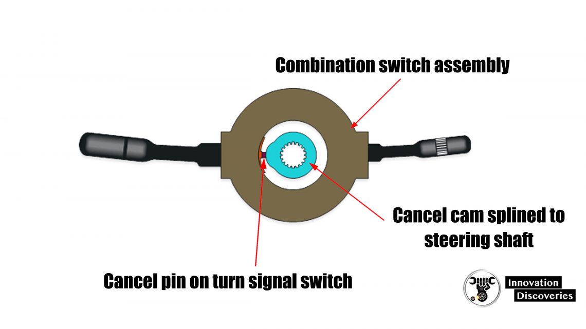
- The canceling cam triggers the turn signal switch to turn off after the turn has been completed.
- If the cancel cam is not positioned properly on the steering shaft the turn signals will not cancel correctly.
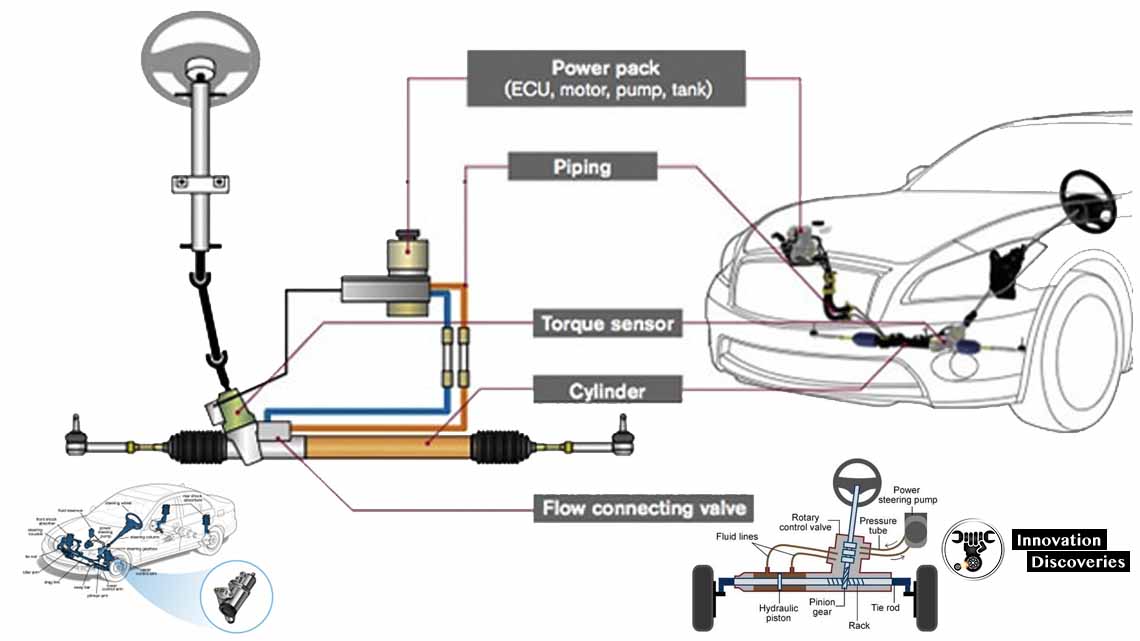
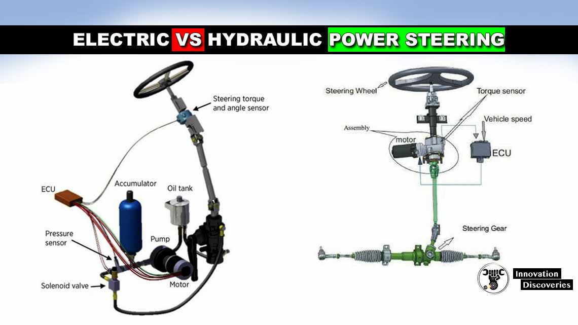
Read: ELECTRIC VS HYDRAULIC POWER STEERING
Read More:
- 3 COMMON SYMPTOMS OF LOW POWER STEERING FLUID
- ELECTRIC VS HYDRAULIC POWER STEERING
- HOW POWER STEERING WORKS?
- STEERING SYSTEM: REQUIREMENTS, TYPES, POWER STEER
Read More:
- HOW CAR SPRINGS AND DAMPERS WORK
- HOW AIR SUSPENSION SYSTEMS WORK
- 5 SUSPENSION MODS YOU SHOULD NEVER DO TO YOUR CAR
- A QUICK GUIDE TO DIAGNOSING 10 COMMON STEERING ISSUES
- 5 WARNING SIGNS OF BAD INTERMEDIATE STEERING SHAFTS
- 3 COMMON SYMPTOMS OF LOW POWER STEERING FLUID
- ELECTRIC VS HYDRAULIC POWER STEERING
- HOW POWER STEERING WORKS?
- STEERING SYSTEM: REQUIREMENTS, TYPES, POWER STEER