“How can I do a quick check on my armature to see if it is ok?”
If you have access to a volt/ohmmeter, there are three quick checks you can do that will tell you if a motor armature is functioning properly.
But first, we must understand some basics of armature design.
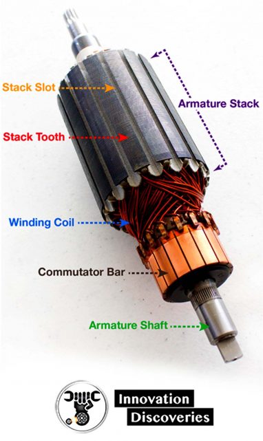
BASIC ARMATURE DESIGN
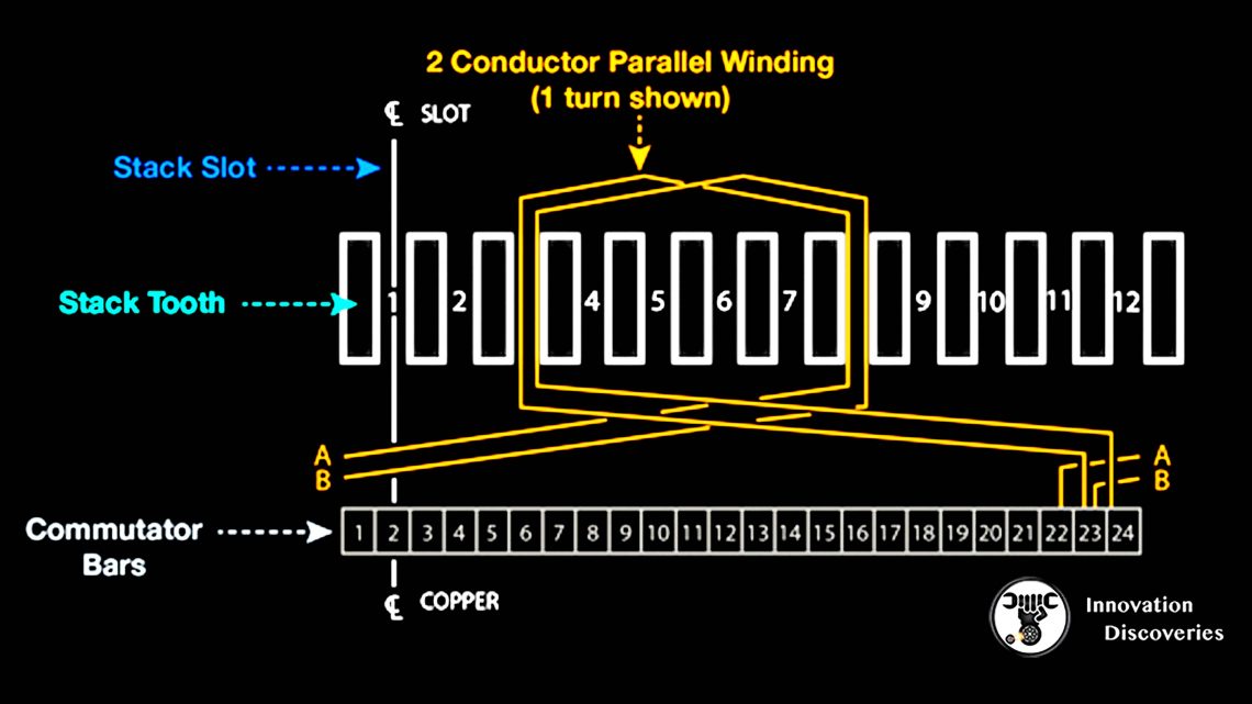
An armature has a continuous series of windings from each bar on the commutator, which loop around the iron stack teeth and connect to the next bar on the commutator.
The winding continues to loop around the armature in the same manner.
Loops are either single or parallel conductors (wires) and can circle any number of times around the stack teeth (called turns in a coil).
The wire can vary in gauge as is required for the design of the motor.
Each wire is insulated with an enamel coating, isolating it from every other wire in the loop, and only terminates at a commutator bar.
The turns in every coil wrap around the iron stack to create an electromagnet.
When energized, an electromagnetic field is generated in the motor armature.
This EM field interacts with the magnetic fields of the permanent magnets in the motor (in the case of a permanent magnet motor) or with the electromagnetic field created by the stator (in the case of a universal motor).
These magnetic forces work to attract each other, inducing a torque on the armature shaft, causing it to turn.
If a motor is driven too hard for its environment and temperatures are allowed to rise beyond the thermal limits of the insulation, it is possible for the insulation on the wires to break down and short together, or short to the armature stack.
If windings are shorted together, the electromagnetic fields cannot be created for that coil, causing the motor to run erratically or fail together.
ARMATURE TEST
#1
To check the condition of the armature windings, the armature will probably have to be removed from the motor.
However, if the motor design has external brush holders, you can unscrew the brush caps and remove the brushes.
Depending upon brush size, this may allow access to the commutator without removing the armature from the motor.
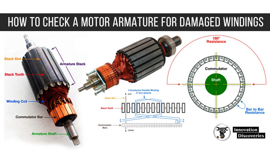
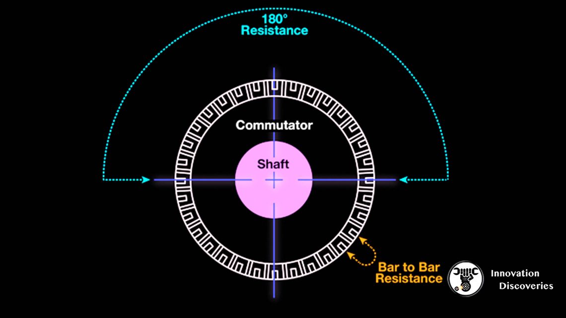
The first check to see if your armature windings are shorted is the “180° Resistance” test.
A volt/ohmmeter can be used to check the resistance of the series windings connected between the two commutator bars of each coil.
Set the meter to measure resistance (Ohms) and then measure the resistance from two commutator bars 180° across from each other.
Rotate the armature and check the resistance between every pair of bars on the commutator.
Figure 3 depicts a 32 bar commutator, so this check must be done between each of the 16 pairs.
The resistance you will measure is dependent upon the number of turns in each coil and the gauge of wire used.
It is also dependent upon the operating voltage for which the motor is designed.
For example, a 90 V dc motor will have smaller conductors and more turns per coil to raise resistance, whereas, a 12 V dc motor will have larger conductors and fewer turns per coil to lower resistance.
Though you probably will not know the armature’s intended resistance value, each measurement should read about the same.
If the resistance drastically varies, there could be a problem with the windings.
A drop in resistance could indicate a short between wires in the coil.
A huge spike in resistance could indicate that a wire is burned through or broken, interrupting the circuit.
#2
The second check is the “Bar to Bar Resistance” test (pictured on right). This will check every coil in the motor armature.
Again, the specific value is based on the motor design (wires per loop, number of turns per coil, and wire gauge).
As with the first test, the important thing to observe is that each measurement should be about the same.
(Note: The resistance you will measure in this test will be much less than in the first test because you will be measuring only one coil.
In the first test, the measurement taken is the resistance of all the coils in series between the two bars.)
Similar to Test #1, a drop in resistance will indicate a short between wires in that coil, and a spike in resistance could indicate a broken or burned wire in a coil.
#3
The third and final test is to measure the resistance of every commutator bar to the iron armature stack.
If the motor armature stack is directly pressed onto the armature shaft, you can use the armature shaft for the measurement.
However, in some cases, even the armature shaft is insulated from the armature stack.
In that case, you will have to measure from each commutator bar to the iron armature stack directly.
In either case, the commutator bars should never have electrical continuity to the armature stack and/or the armature shaft.
If any of these measurements fail, it can be assumed that the armature is damaged.