Types of gearing:
Various types of gearing are used on a motor vehicle. The gearboxes employ one or more of the following:
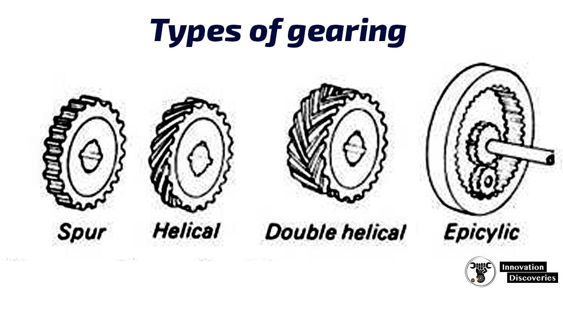
- Spur, teeth parallel to the axis, used on sliding mesh.
- Helical, teeth inclined to axis to form helix.
- Double helical, two sets of opposing helical teeth.
- Epicyclic or planetary, spur or helical gears rotating about centres that are not stationary.
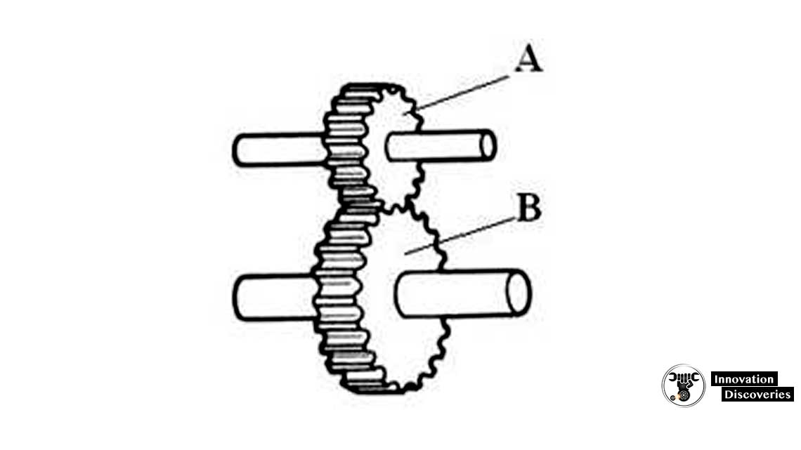
Gear ratio (single gear train):
The gear ratio, or velocity ratio, between a pair of gear wheels is in inverse ratio to the number of teeth on each. Thus:
NB/NA = DA/DB= nA/nB
NB = NA (nA/nB)
Where:
NA= rev per min of gear A, nA = number of teeth on A
NB = rev per min of gear B, nB = number of teeth on B
DA = Diameter of gear A
DB = Diameter of gear B
ALSO, READ: GEAR RATIO AND TIRE SIZE CHART
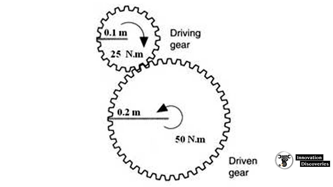
Power, Speed, and Torque:
The power transmitted by a shaft is directly proportional to the speed of revolution and the torque acting on it
Power [kW] = 2 p N T / (60 x 1000) [N.m/s]
Then
TA NA = TB NB
For a given power, therefore, the torque is inversely proportional to the speed of revolution and if their min is reduced the torque will be increased in the same ratio (assuming 100% gear efficiency).
TB/TA = nB/nA
Where:
TA = torque transmitted by A
TB = torque transmitted by B
Velocity or gear ratio (ig) = number of teeth on driven gear/number of teeth on driver gear.
TB = TA (nB/nA) = TA/ ig
READ MORE: TORQUE AND BHP EXPLAINED
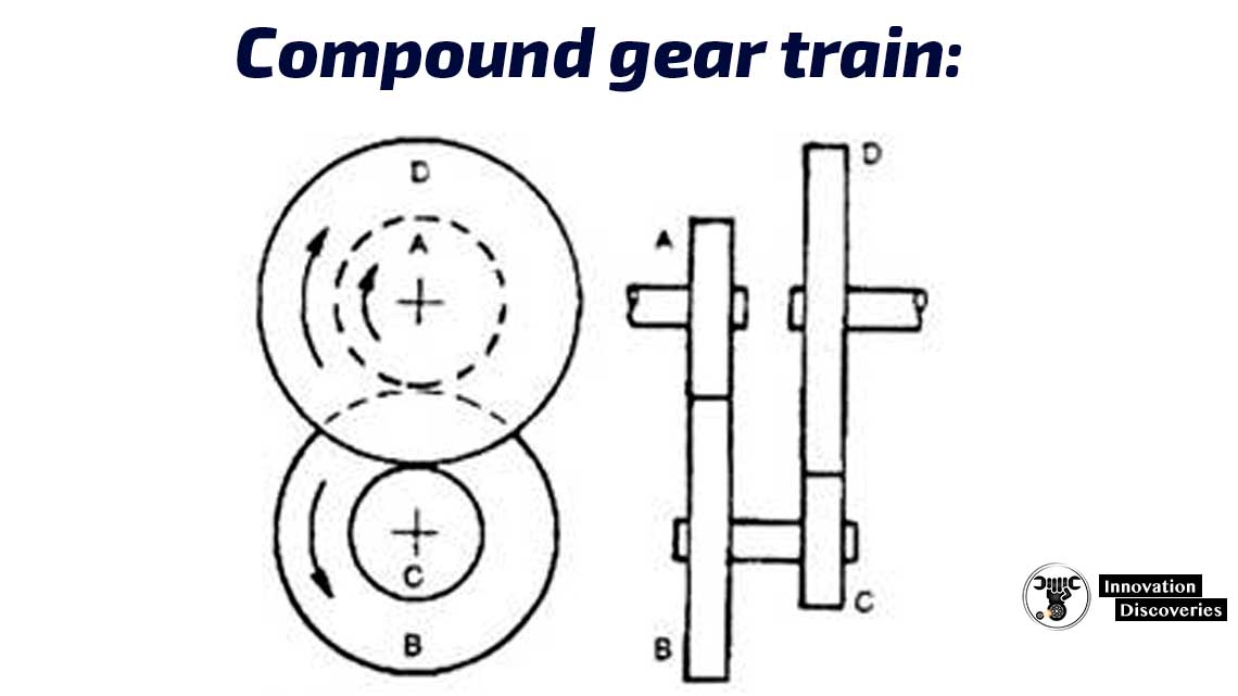
Compound gear train:
If the number of teeth on each wheel is known, the relationship between the speed of wheels A and D can be determined as follows
For wheels A and B: NB/NA = nA/nB, i.e. NB= NA (nA/nB)
Wheel B and C are fixed on the same shaft, so NC=NB
For wheels C and D: ND/NC = nC/nD, i.e. ND = NC (nC/nD)
Substituting NC = NB = NA (nA/nB) from above, we get
ND = NA (nA/nB) (nC/nD)
Or ND/NA =
By inspection of the layout of the figure, it will be observed that wheels A and C are driver gears while B and D are driven gears. Hence, from the above equation
Velocity or gear ratio (ig) = product of teeth on driven gears/ product of teeth on driver gears
ND = NA (nA/nB) (nC/nD) = NA (nA nC / nB nD) = NA/ig
Example:
A double reduction set of gearing is as shown in the above figure. Wheel A is the driver gear, wheels B and C fixed to the same shaft, and wheel D is the final gear in the train. The number of teeth on each wheel is A=20, B=50, C=40, D=30 teeth.
a- Determine the velocity ratio of the gearing system.
b- Calculate the speed of rotation of wheel D when wheel A rotates at 1800 rev/min.
c- Calculate the torque of wheel D when the torque of A is 100 N.m and the efficiency of the gear train is 90%.
a- Velocity ratio = product of teeth of driven gears/ product of teeth on driver gears
i.e. velocity ratio (ig) = (nD nB / nC nA) = (30 x 50) / (20 x 40) = 1.875
b- ND = NA / ig = 1800 / 1.875 = 960 rev/min
c- TD = TA ig hg = 100 x 1.875 x 0.9 = 168.75 N.m
Types of Drives and gearboxes
There are many types of car drives, usually classified by a number of driving axles (4×2, 4×4, 4WD, AWD) and each type has a different gearing arrangement.
Also, gearbox (transmission) has different types (sliding-mesh, constant-mesh, synchro-mesh) some of them are old-fashion and had been replaced, and some are in use in modern cars.
READ MORE:
- HOW MANUAL GEARBOXES WORK
- MANUAL OR AUTOMATIC GEARBOX: WHICH IS THE BEST?
- WHAT HAPPENS WHEN YOU SKIP GEAR IN A MANUAL TRANSMISSION?
- WHEN TO SHIFT GEARS FOR THE BEST FUEL ECONOMY
- THE ADVANTAGES AND DISADVANTAGES OF STRAIGHT CUT GEARS
- WHEN TO PUT YOUR VEHICLE IN 4-WHEEL DRIVE?
SLIDING-MESH GEARBOX:
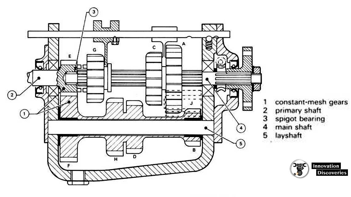
The sliding gearbox was popular on cars up to about 1930, but it is rarely used. The basic layout of a 4-speed and reverse gearbox is shown in the figure. The various spur-type gears are mounted on three shafts.
- Primary shaft (alternative names – clutch or first motion shaft)
- Layshaft (countershaft)
- Mainshaft (third motion shaft).
READ MORE:
- SLIDING MESH GEARBOX – MAIN PARTS, WORKING AND APPLICATION
- HOW TO FIX AN AUTOMATIC TRANSMISSION THAT IS SLIPPING
- HOW A CAR CLUTCH WORKS
Primary shaft
This shaft transmits the drive from the clutch to the gearbox. In the end, the shaft is supported by a spigot bearing positioned close to the splines on to which the clutch driven plate is connected.
The main load on this shaft is taken by a bearing; normally a sealed radial ball type is positioned close to an input gear called a constant mesh pinion.
The gear is so named because it is always in mesh with a larger gear, a c constant mesh wheel, that I part of the layshaft gear cluster.
Note that a small driving gear is called a pinion and a large gear a wheel.
Layshaft
This shaft, which is normally fixed to the gearbox casing, supports the various-sized driving pinions of the layshaft gear cluster.
Main shaft
This splined output shaft carries spur gearwheels that slide along the shaft to engage with the appropriate layshaft gears.
At the ‘front’ end, the main shaft is supported by a spigot bearing situated in the center of the constant mesh pinion.
A heavy-duty radial ball bearing is fitted at the other end to take the force of the gears as they attempt to move apart.
READ MORE: FULL NOTES ON SYNCHROMESH GEARBOX
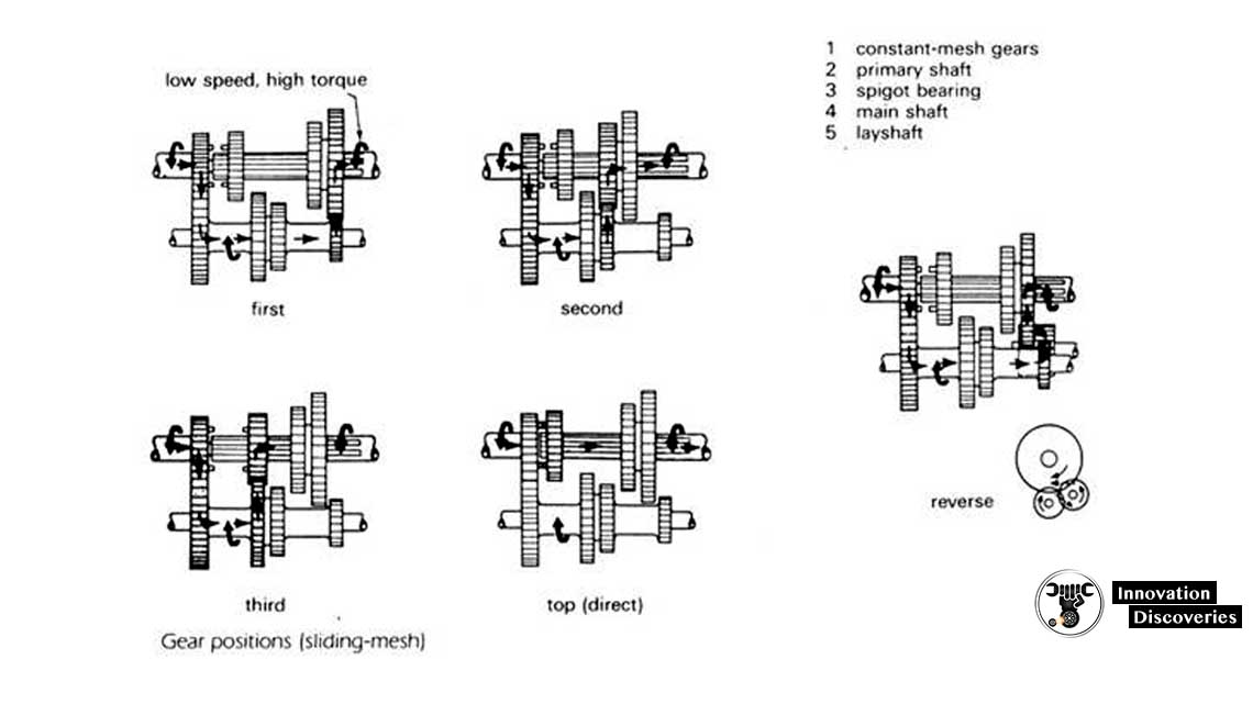
Gear positions
Neutral
All main shaft gearwheels are positioned so that they do not touch the layshaft gears.
A drive is taken to the layshaft, but the main shaft will not be turned in the neutral position.
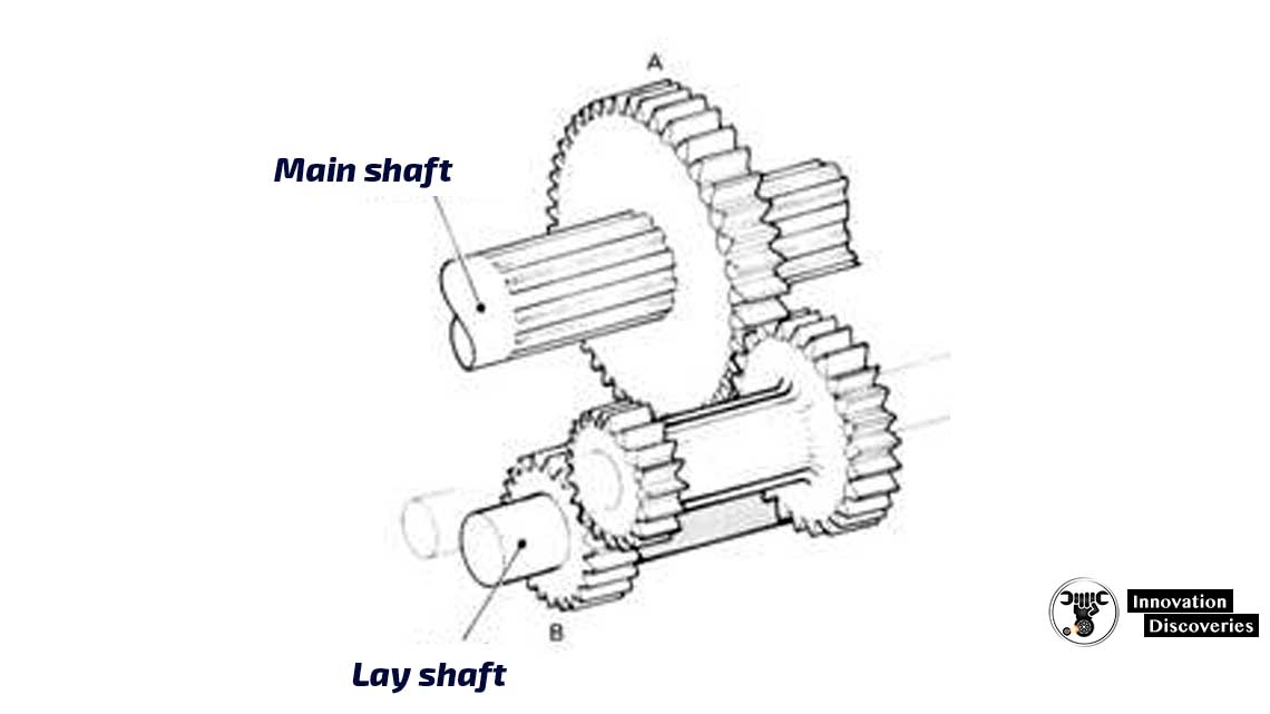
First gear
The first-speed gearwheel A on the main shaft is lid backward to engage with pinion B on the layshaft; all other gears are positioned in neutral.
In this gear, the reduction in speed that occurs as the drive passes through the constant-mesh gears, E and F, is reduced further by the first-speed gears, A and B.
The gear ratio (also called the movement ratio or velocity ratio) is given by
Ratio = (Driven/driver) x (driven/driver)
Ig1 = (F/E) x (A/B)
Noutput 1 = Ninput / ig1
Toutput 1 = Tinput x ig1 x hg1
Second gear
The second-speed gearwheel C is slid forward to engage with the layshaft gear D; all the other gear is set in the non-driving position.
Ig2 = (F/E) x (C/D)
Third gear
In this gear position, gearwheel G is slid in to mesh with gear H.
Ig3 = (F/E) x (H/G)
Top gear
In this layout, the fourth gear is a direct drive; namely a gear that gives a ratio of 1:1.
It is obtained by sliding gear G to engage its dog teeth with the corresponding teeth formed on the end of the constant mesh pinion E.
Engagement of the dog clutch locks the primary to the main shaft and this gives a ‘straight-through’ drive.
Reverse gear
Sliding a reverse gear between any two gears on the layshaft and main shaft is the method used to change the direction of rotation of the output shaft.
The simplest arrangement uses a single reverse gear, which is mounted on a short shaft.
This shaft is positioned so that the reverse can slide and mesh with the two first-speed gears as shown in the figure.
The gear ratio is
igr = (Driven/Driver) x (Driven/Driver) x (Driven/Driver)
= (F/E) x (J/B) x (A/J)
= (F/E) x (A/B)
This is the same ratio as for first gear, and irrespectively of the size of gear J, it will be seen that the ratio always remains the same.
For this reason, it is called an idler – it changes the direction, but does not alter the ratio.
With the idler arrangement, some drivers persistently slip the clutch to maintain a low reversing speed.
Excessive clutch wear resulting from this practice is minimized when the reverse ratio is set lower than the first gear.
This is achieved by using a reverse gear arrangement as shown in the figure. Instead of the single idler, the compound reverse gear has two gear pinions joined together.
The reverse shaft is positioned so that the reverse pinions can mesh simultaneously with the appropriate layshaft and main shaft gears.
Gear Changing
When one gear is moved to engage with another gear noise will result if the peripheral (outside) speeds are not the same to avoid this, the driver of the vehicle having a sliding-mesh gearbox performs an operation called double-declutching.
Select mechanism
A fork of the type shown in the figure is used to slide a gearwheel along the main shaft to select the appropriate gear.
It is mounted on its own rod and links the driver’s gear stick to the sliding gearbox. Every gearbox must be fitted with the following:
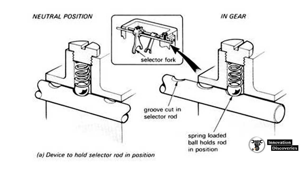
1- Selector detent–
Holds the gears and selectors in position and so prevent gear engagement or disengagement due to vibration.
The figure shows a typical arrangement suitable for a layout having the selector fork locked to the rod.
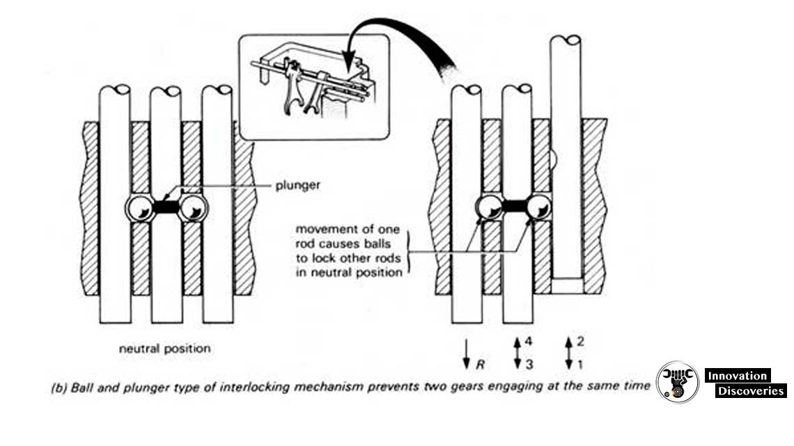
2-Interlock mechanism–
Prevents two gears from engaging simultaneously; if this occurs the gearbox will lock up and shaft rotation will be impossible.
Although the interlock device takes a number of different forms, the arrangement shown in the figure is one of the most common.
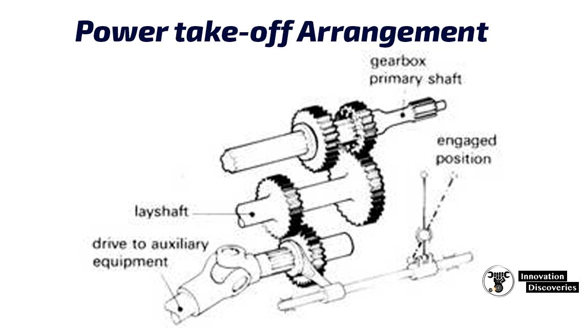
Power take-off arrangement
In addition to the machine used for driving a vehicle along a road, a power supply is often required for operating external items of auxiliary equipment.
A light truck having a tipping mechanism is one example, but the most varied application of power take-off units is associated with specialized off-road vehicles.
The figure shows a typical power take-off arrangement that is driven by the gearbox layshaft.
Disadvantages of the sliding mesh
Although the mechanical efficiency of the sliding mesh gearbox was high, it suffered from two great disadvantages:
- Gear noise due to the type of gear.
- The difficulty of obtaining a smooth, quit, and quick change of gear without great skill and judgment.
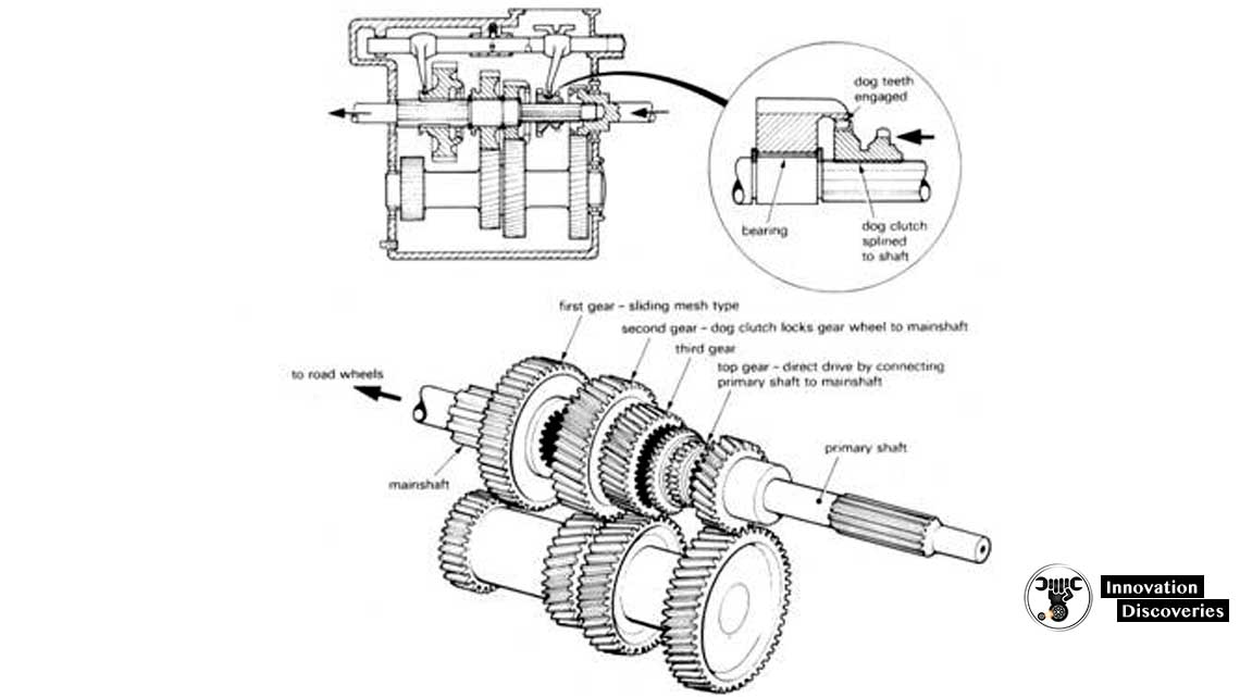
CONSTANT-MESH GEARBOX
The main feature is the use of the stronger helical of double-helical gears which lead to quieter operation.
In this design, the main shaft pinions revolve freely on bushes or needle-roller bearings and are all in constant engagement with the corresponding layshaft wheels.
The gear operation is obtained by locking the respective gear to the main shaft by means of a dog clutch.
The layout of the box is shown in the figure.
With this arrangement, the quieter-running helical gears can be employed, and during gear changing the noise and wear are reduced by the simultaneous engagement of all the dogs instead of only a pair of gear teeth as on the sliding-mesh gearbox.
With single helical pinions (double helical is economically impractical), the driving loads on the teeth cause an axial thrust which must be resisted by thrust washers, or shoulders, on the main shaft.
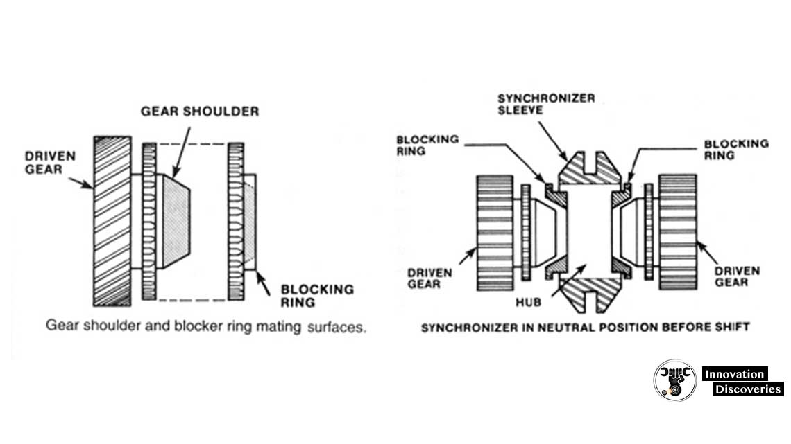
CONSTANT-LOAD SYNCHRO-MESH
The figure shows unite the main details.
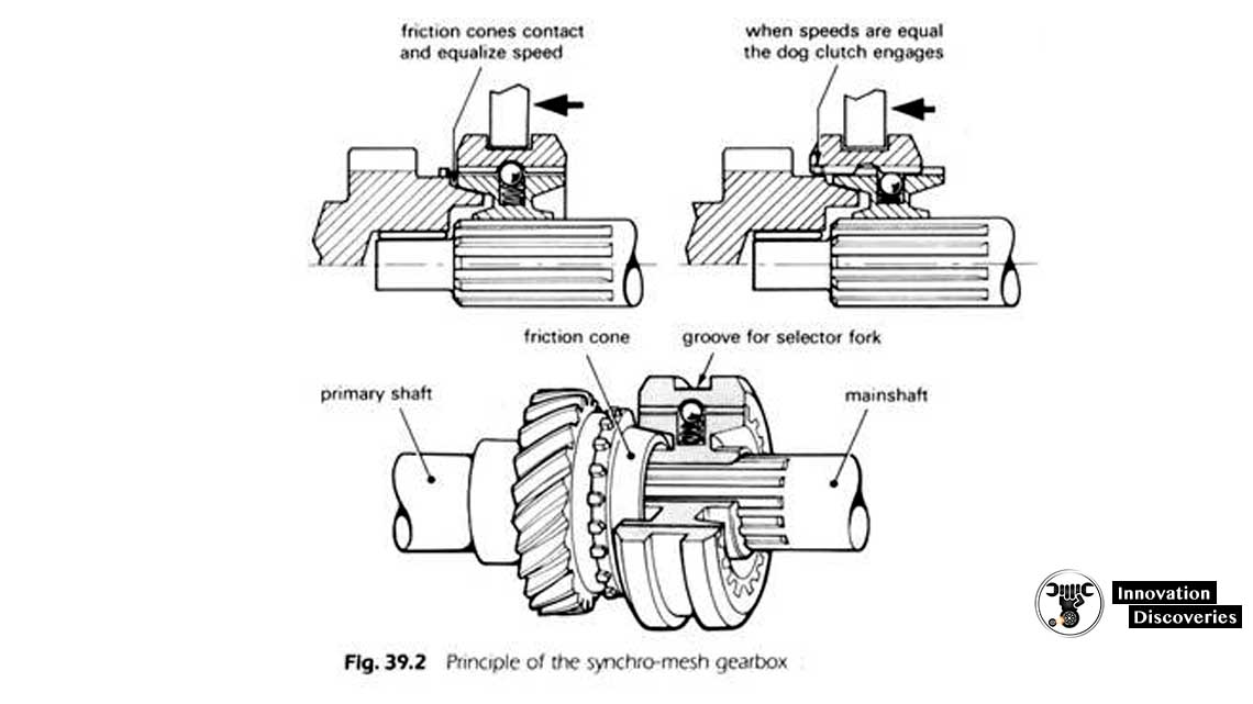
Fundamentally the box is laid out in the same manner as a constant-mesh, with the exception that a cone clutch is fitted between the dog and gear members.
The initial movement of the selector a sleeve carries the hub towards the gear and allows the cones to adjust the speed of the gearwheel to suit the hub and main shaft.
Extra pressure on the lever will allow the sleeve to override the spring-loaded balls and positively engage with the dogs on the gear.
BAULK RING SYNCHRO-MESH
This system is designed to overcome the main disadvantage of the earlier design- noise or crashing of the gears due to a quick change, by adding the balking ring to do the job as shown in the figure.
ADDITIONAL GEAR RATIOS
Commercial vehicles having a relatively low power/weight ratio, and operating under unladen to fully loaded conditions, require additional gears for efficient operation.
ALTERNATIVE RATIO GEARBOX:
A-One arrangement is to provide two pairs of alternative-ratio constant mesh gears between the clutch shaft and layshaft.
This doubles the number of indirect gear ratios available.
B- Another system is to use an auxiliary gearbox behind the main gearbox with a choice of direct drive or a reduction to split the ratios in the main gearbox.
This enables all the available gears to be used in sequence.
The auxiliary gearbox may be a layshaft type with constant-mesh gears, or epicyclic, and the gear change may be power-operated electrically or by compressed air.
OVERDRIVE GEAR:
Sometimes, and particularly, for cars where the economy with a lowered cursing engine speed is desired, the epicyclic unit may provide an overdrive of approximately 0.75:1.
More recent practice is to incorporate fifth speed an indirect ratio of some 0.75:1 to 0.85:1. A typical arrangement is an extra pinion on the layshaft in constant mesh with a mineshaft pinion turning on needle-roller bearings.
This is engaged by a synchromesh unit splined to the main shaft and operated from the reverse selector.
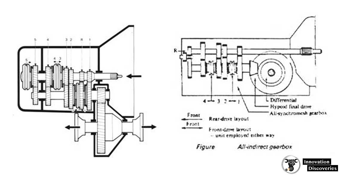
THE ALL-INDIRECT GEARBOX (TRANSAXLE):
The layshaft two-stage gearbox is used in both longitudinal- and transverse-engined front-wheel-drive case.
However, many of the former employs a single-stage, all-indirect gearbox.
There is no direct drive and consequently no particular advantage in the 1:1 gearbox ratio.
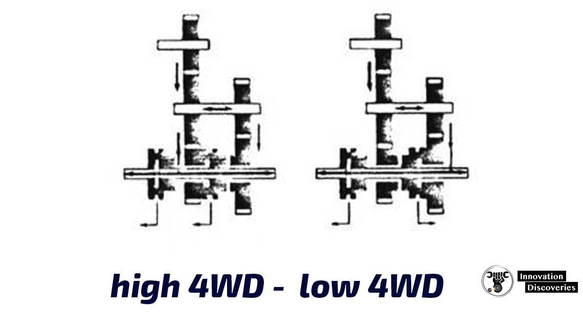
TWO-SPEED TRANSFER GEARBOX:
A range of vehicles uses optional four-wheel drive- with additional ‘emergency’ low ratios- to provide a cross-country facility.
This is usually accomplished by a two-speed transfer gearbox. With layshaft and two pairs of constant-mesh helical gears, attached to the end of the main gearbox are driven via a short coupling shaft from the gearbox main shaft.
Four- and All-Wheel Drive:
Four-wheel-drive (4WD) and all-wheel-drive (AWD) systems can dramatically increase a vehicle’s traction and handling ability in the rain, snow, and off-road driving.
The improved traction of 4WD and AWD systems allows the use of tires narrower than those used on similar 2WD vehicles.
These narrow tires are less expensive. They also tend to cut through snow and water rather than hydroplane over it. Both 4WD and AWD systems add initial cost and weight.
4WD versus AWD:
4WD systems are those having a separate transfer case.
They also give the driver the choice of operating in either 2WD or 4WD through the use of a shift lever or shift button.
AWD systems do not have a separate transfer case.
They use a front-wheel-drive transaxle equipped with a viscous clutch, center differential, or transfer clutch.
An All-Wheel-drive system does not give the driver the option of selecting 2WD or 4WD modes.
The system operates in continuous 4WD. All-wheel-drive vehicles are usually passenger cars that are not designed for off-road operation.
They are designed to increase vehicle performance in poor traction situations, such as icy snowy roads, and emergencies.

4 Comments