This article will explore:
- Automatic Transmission System Layout
- Torque Converter Construction and Operation
- Planetary Gear Construction and Operation
- Clutches, Bands, and Servos
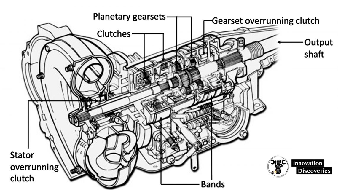
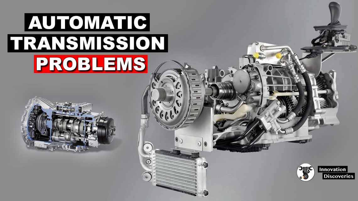
Basic Automatic Transmission System
The basic components of an automatic transmission system are:
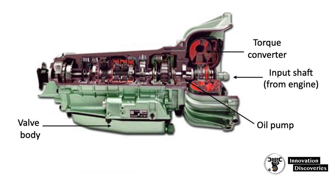
- Torque Converter – Fluid coupling that connects the engine to the transmission.
- Oil Pump – Produces hydraulic oil pressure to operate the hydraulic components.
- Valve Body – Mounted inside pan, controls oil flow to pistons and servos.
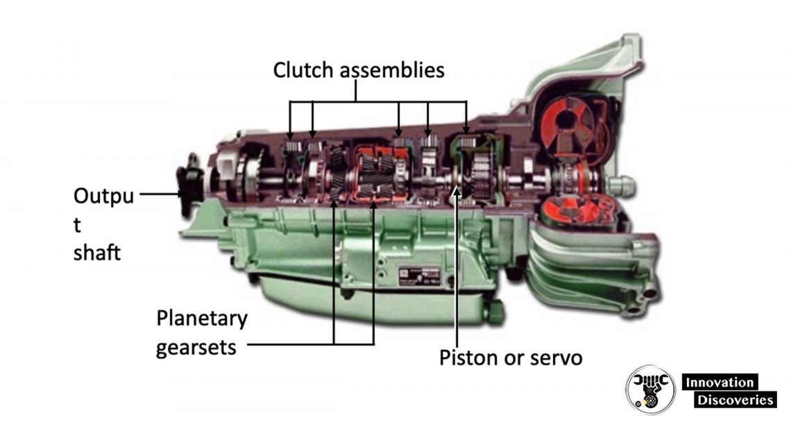
- Pistons and Servos – Operate bands and clutches, selecting ratios.
- Planetary (Epicyclic) Gearsets – Provide gear ratios and reverse.
- Bands and Clutches – Actuate planetary gearsets by clamping pressure.
- Output Shaft – Transfers torque to the drive shaft.
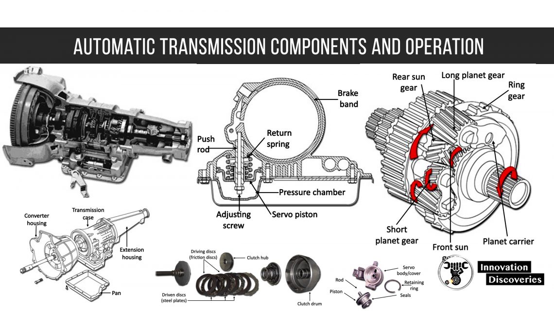
Transmission Housing
There are four main components to the transmission housing:
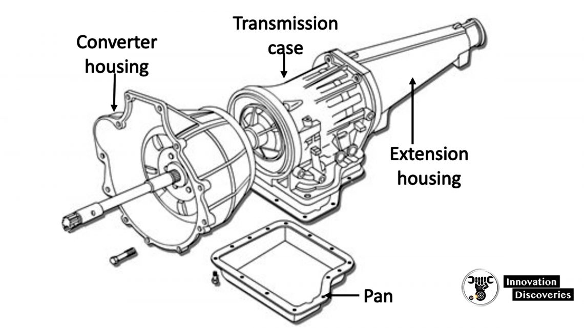
- Converter Housing – Attaches the transmission to the engine, houses the converter, and is usually made of aluminum.
- Transmission Case – Holds the components of the transmission system.
- Oil (Transmission) Pan – Holds the hydraulic oil and is sealed by a gasket.
- Extension Housing – Protects and houses the output shaft and is sealed by a gasket.
Torque Converter Principle
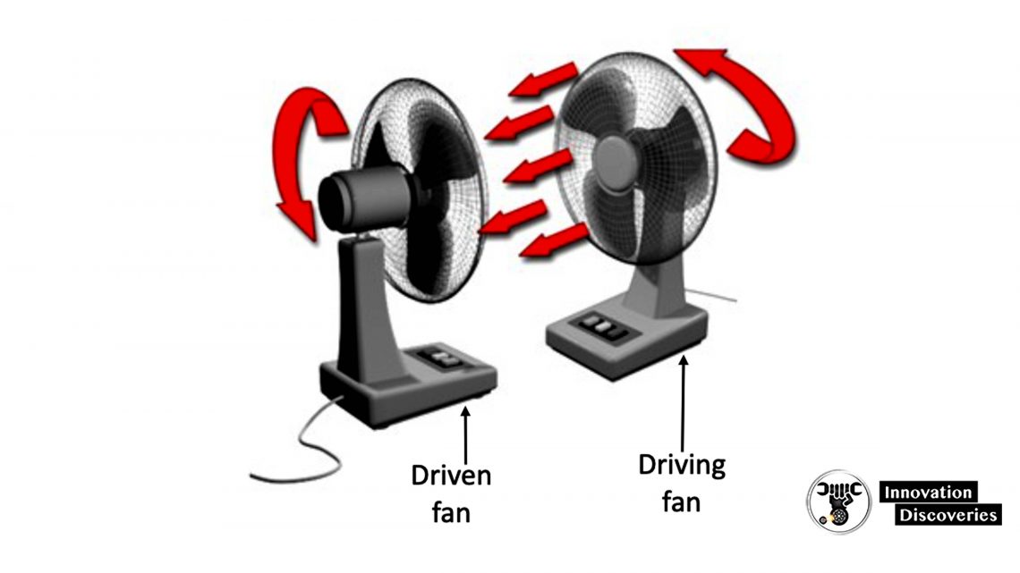
The torque converter couples the engine to the transmission.
It’s the principle of operation that can be demonstrated by two electric fans.
One fan power cord is connected to the AC supply and faces the other.
The airflow created by this fan causes the second fan to rotate, even though it is not connected to the supply.
A torque converter uses oil instead of air to perform the turning motion.
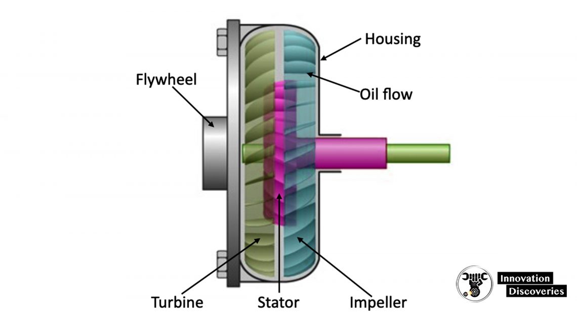
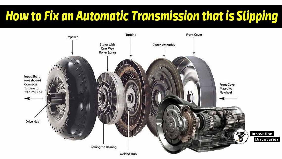
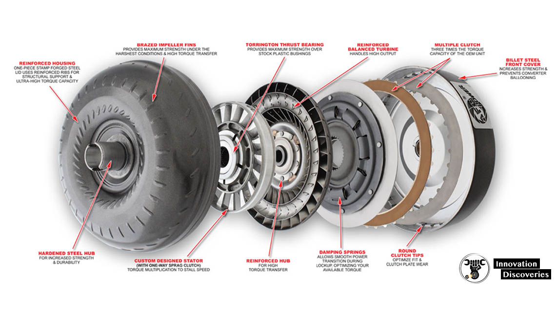
Torque Converter Construction
The torque converter is not a serviceable item. Its main components are:
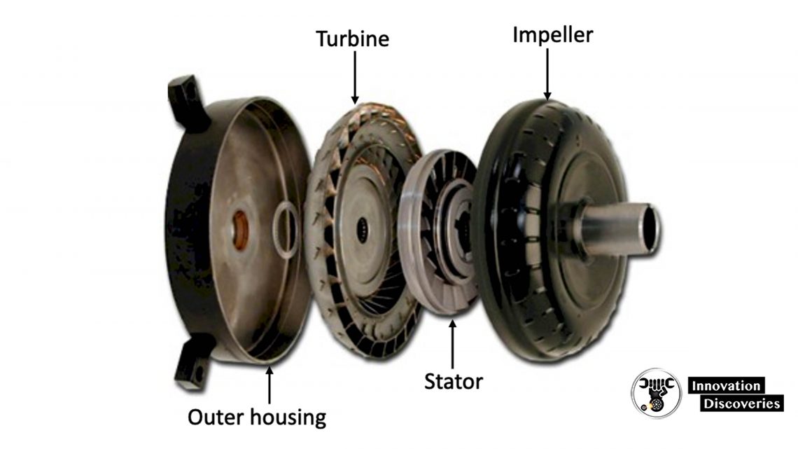
- Converter Housing – Made from two parts, an outer housing, and an impeller. They are precision welded together and oil-filled.
- Impeller – (Driving fan) provides power to drive a turbine. It contains blades that direct oil flow.
- Turbine – (Driven fan) contains blades that receive oil and redirect it, to produce a turning force.
- Stator – Redirects oil flow from turbine to impeller, using blades.
Torque Converter Operation
The converter housing is bolted to the flywheel of the engine. The housing and the impeller, therefore, turn at engine speed.
As the impeller spins, oil is flung outward. A vacuum is created in the center of the impeller, which draws in more oil.
The turbine is connected to the input shaft of the transmission system. It is turned by oil entering its blades.
The blades force the oil toward the center of the turbine.
Oil exits the turbine in the opposite direction from impeller rotation, due to turbine design.
The stator is designed to redirect oil flow so that it assists the impeller. It can only spin in one direction, against turbine oil flow.
At low engine speeds, the turbine turns at a lower speed than the impeller, producing a gain in output torque.
This is ideal for moving a vehicle from stop (or during acceleration), when an engine is not operating at its full potential.
This is known as torque multiplication.
As engine speed increases, torque multiplication reduces until the speed of the turbine approaches that of the impeller (3000 RPM plus).
The engine power characteristics then compensate for the loss of torque multiplication.
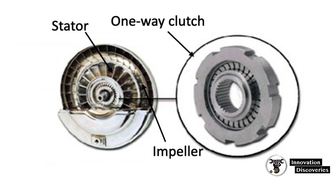
Stator One-Way Clutch Operation
The stator rotates in one direction only. It is locked by an overrunning (one-way) clutch mechanism.
This method may be used on other gearsets, within the transmission system.
Operation
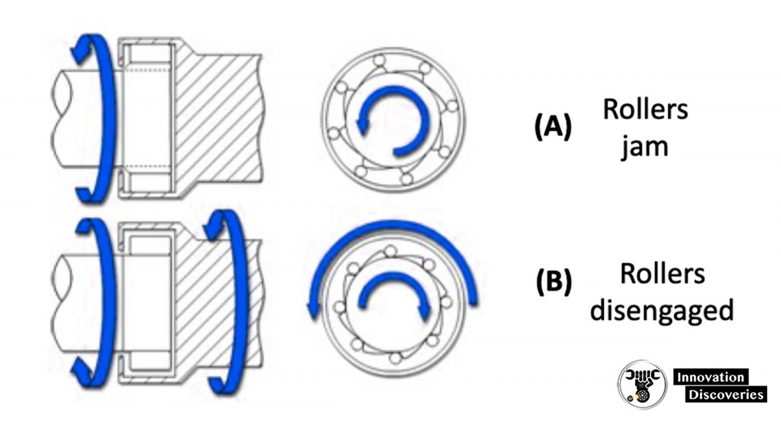
When the shaft tries to turn counter-clockwise, the rollers ride up on the cams and lock up (A), preventing opposite rotation.
When the shaft turns clockwise, the rollers return to their disengaged position (B) allowing the shaft to turn freely.
Lockup Torque Converters
At higher engine speeds, the transmission is moving at nearly the same speed as the engine.
In an ideal situation, they should be traveling at the same speed, because speed difference (slippage) equals power loss.
This is part of the reason why vehicles with automatic transmissions use more fuel, than those with manual versions.
Some manufacturers overcome this problem by using a lockup torque converter. A typical converter contains a clutch, friction discs, and pads.
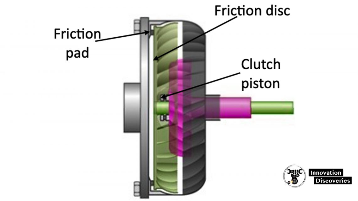
When the turbine and the impeller are up to speed, fluid is channeled to the clutch piston.
Piston action pushes the friction discs/pads together, locking the turbine and impeller to turn as one.
The converter may be fitted with torsion springs to dampen engine power pulses.
This system improves efficiency and prevents slippage.
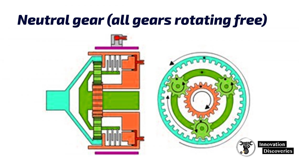
Planetary Gears
In an automatic transmission, planetary gearsets are used to provide forward and reverse gear ratios.
The gears rotate but never move in a lateral direction.
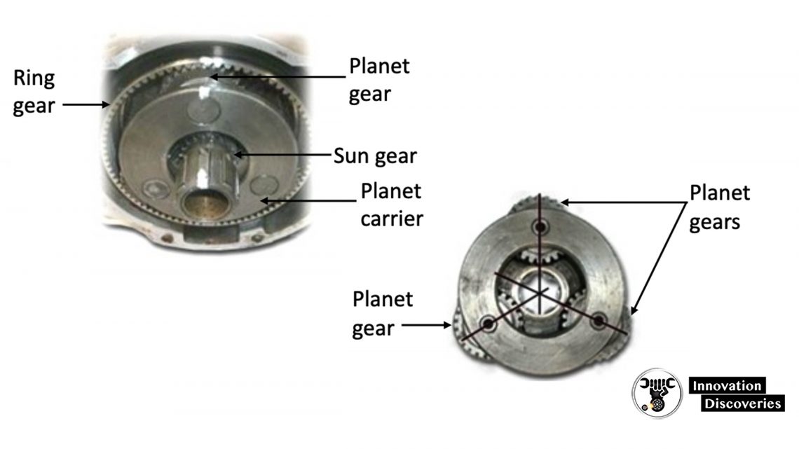
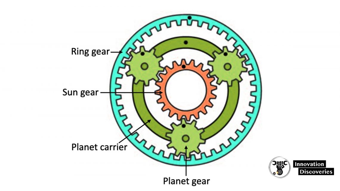
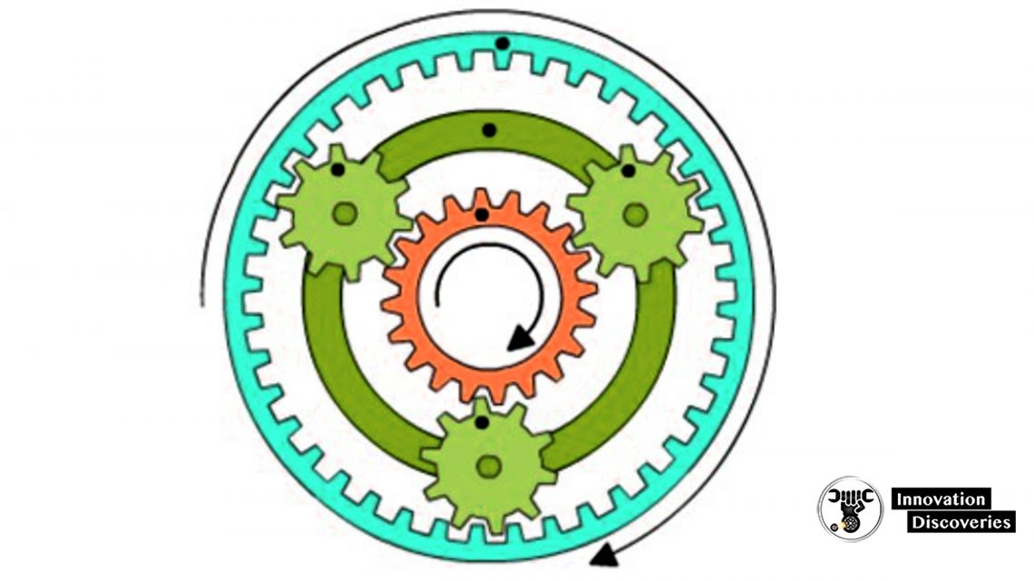
The basic planetary gear set consists of a sun gear, a ring gear, and planet gears.
- Sun Gear – Middle gear around which the other gears revolve.
- Planet Gears – Usually two or more gears that mesh with, and revolve around the sun gear. They are held together using a planet carrier.
- Ring Gear – Surrounds and meshes with the planet gears.
Planetary Gears – Movement Examples
By clamping or releasing some of these revolving gears, a combination of different gear ratios may be produced on the output shaft.
Typical examples:
- Ring gear clamped – sun gear and planet carrier both rotate in the same direction (e.g. clockwise).
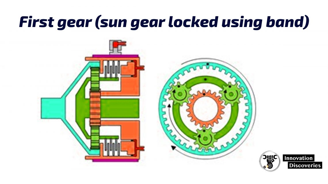
- Sun gear clamped – planet carrier and ring gear both rotate in the same direction (e.g. clockwise).
- Planet carrier clamped – sun gear rotates in one direction (e.g. clockwise), the ring gear rotates in the other direction (e.g. counter-clockwise).
Planetary Reduction
When the output shaft rotates slower than the input shaft, an increase in output torque is achieved. This is obtained by using gear reduction.
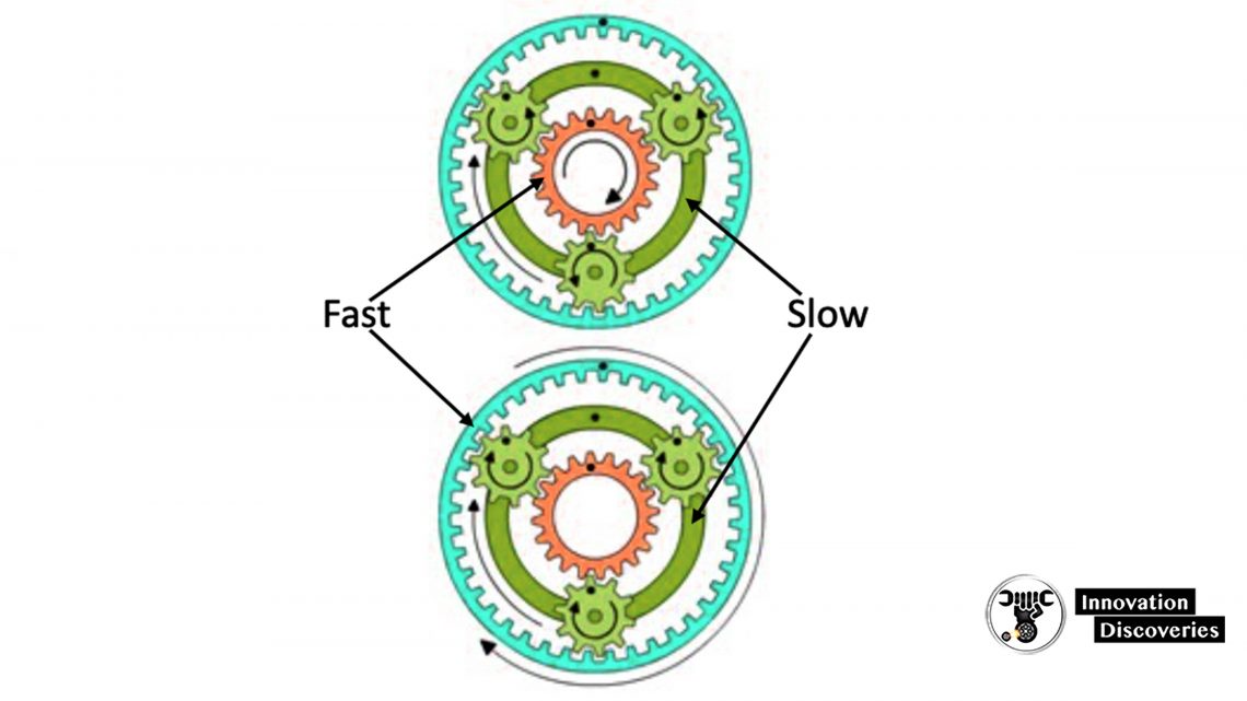
There are two typical methods:
- Sun gear clamped – Input is applied to the ring gear, the planet gears move around the sun gear, the planet carrier is the output.
- Ring Gear – Input (Driven)
- Planet Carrier – Output
- Sun Gear – Clamped
- Ring gear clamped – Input is applied to the sun gear, the planet carrier is turned by the planet gears to become the output.
- Ring Gear – Clamped
- Planet Carrier – Output
- Sun Gear – Input (Driven)
In both cases, the direction of input and output rotation is the same.
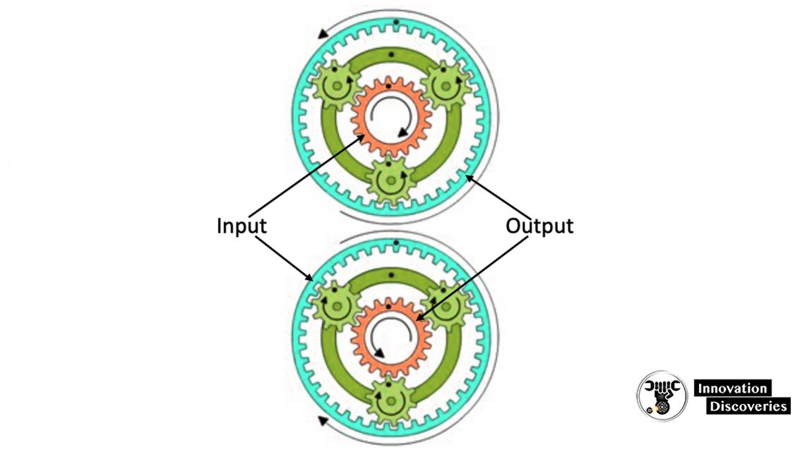
Overdrive
When the output shaft rotates faster than the input shaft, an increase in vehicle speed is achieved, at the cost of reduced output torque.
This is obtained by using Overdrive.
There are two typical methods:
- Ring gear clamped – Input is applied to the planet carrier and the output is taken from the sun gear.
- Ring Gear – Clamped
- Planet Carrier – Input (Driven)
- Sun Gear – Output
- Sun gear clamped – Input is applied to the planet carrier and the ring gear is turned by the planet gears to become the output.
- Ring Gear – Output
- Planet Carrier – Input (Driven)
- Sun Gear – Clamped
Reverse
- Planet carrier clamped – The input is applied to the sun gear and the output is taken from the ring gear.
- Ring Gear – Output
- Planet Carrier – Clamped
- Sun Gear – Input (Driven)
- Planet carrier clamped – The input is applied to the ring gear and the output is taken from the sun gear.
- Ring Gear – Input (Driven)
- Planet Carrier – Clamped
- Sun Gear – Output
In both cases, the output will turn in the opposite direction from the input.
Direct Drive
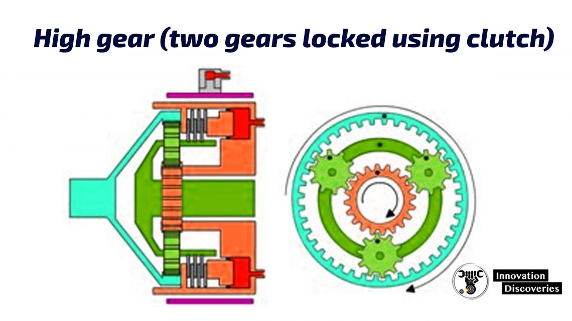
If two gears are locked together, the third gear is directly driven by the other two.
This is known as direct drive. In the diagram to the right, the sun gear and planet carrier are locked together.
The ring gear is forced to rotate at the same speed as the locked gears.
Compound Planetary Gearset
The gears found in a real transmission system are more complex than the examples just discussed.
A compound planetary gearset can give a wider range of gear ratios.
It has two planetary gearsets inside a single case and/or ring gear. The ring gear couples with both planet sets.
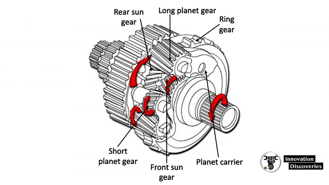
Some may have two sun gears, as shown to the right.
Short planet gears mesh with the front sun gear and long planet gears mesh with the rear sun gear.
One of the most common types is the Simpson Compound Gearset.
This type has one sun gear, two planet gearsets, and one ring gear.
Clutches and Bands
Clutches and bands are the devices that use friction to clamp or lock the required components of planetary gearsets to give the required gear ratios.
Clutch Construction
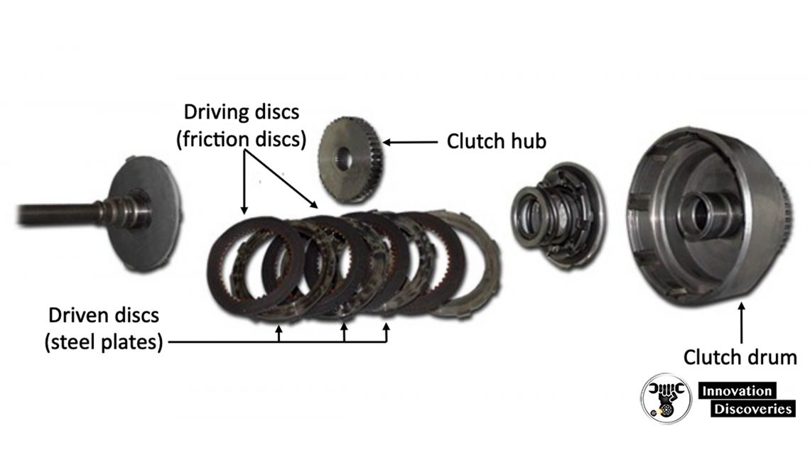
- Clutch drum Clutch (Cylinder) Drum – Encloses the clutch components.
- Clutch Hub – Fits inside the clutch drum. It also fits inside the diving discs. It has teeth on its outer edge that mesh with those of the driving discs.
- Driving Discs – They are friction lining covered and have teeth that mesh with the clutch hub.
- Driven Discs – These have outer tabs that lock into the clutch drum.
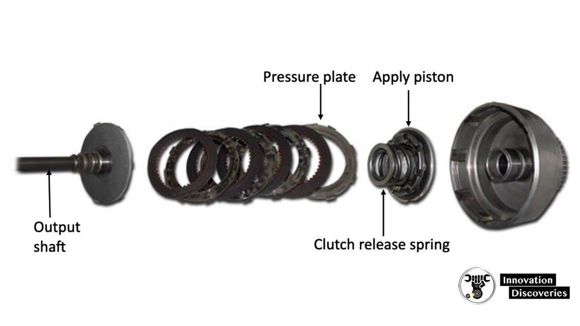
- Clutch Apply Piston – By the use of hydraulic pressure. This clamps the driven and driving discs together. Oil seals prevent fluid from leaking from the piston when the clutch is applied.
- Pressure Plate – This limits the travel of the clutch discs allowing plates to be clamped together when the piston activates the clutch.
- Clutch Release Spring – Returns the applied piston to its rest position when hydraulic pressure is released and the clutch is disengaged.
Clutch Operation
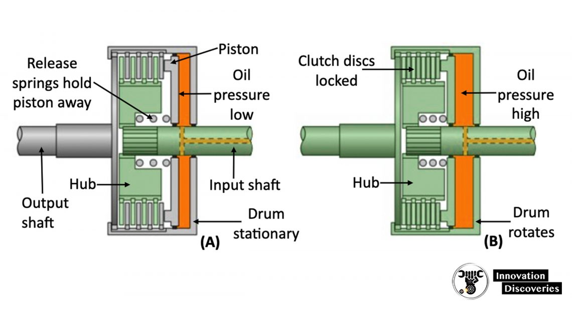
With no hydraulic pressure applied, the release springs hold the driving and driven discs disengaged and free to revolve independently of each other (A).
The input shaft drives the clutch hub, but not the drum or output shaft.
When hydraulic pressure is applied, the piston forces the driving discs and the driven discs together to clamp the hub to the drum so that they turn together (B) as one unit.
Brake Bands
Brake bands are friction devices used to lock clutch drums and ring gears in position.
The friction material resists the lubrication properties of the transmission oil. The brake band fits around a clutch drum or ring gear.
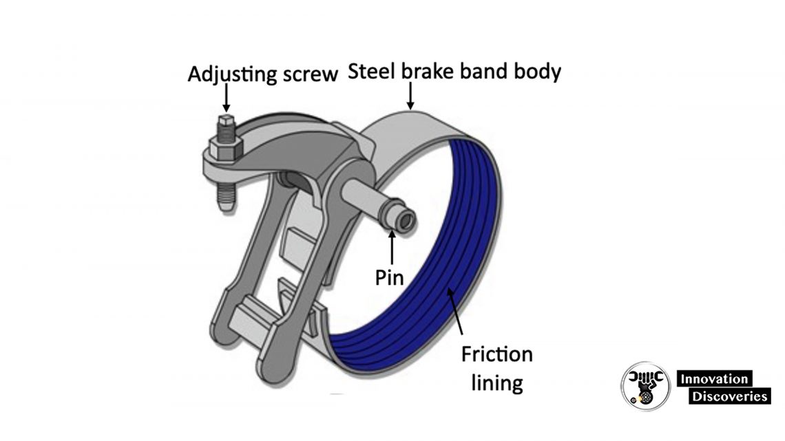
It is tightened by the movement of a push rod, which protrudes from the piston of a servo.
Servo body/cover Several brake bands are commonly used in automatic transmissions. An adjusting screw is provided for initial adjustment and to compensate for lining wear.
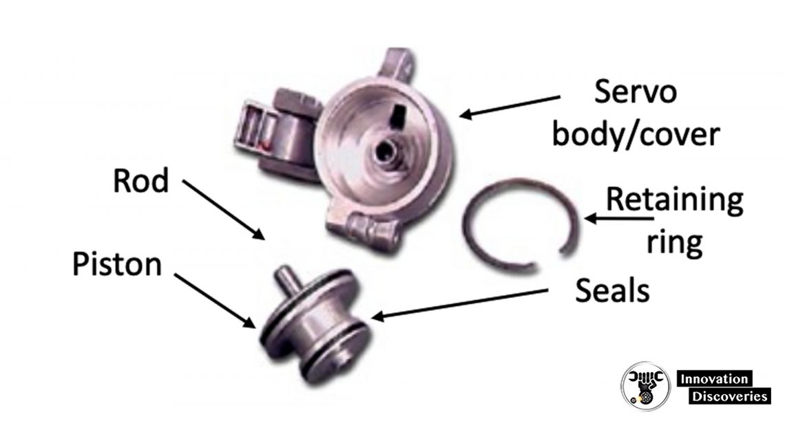
Brake Band Operation
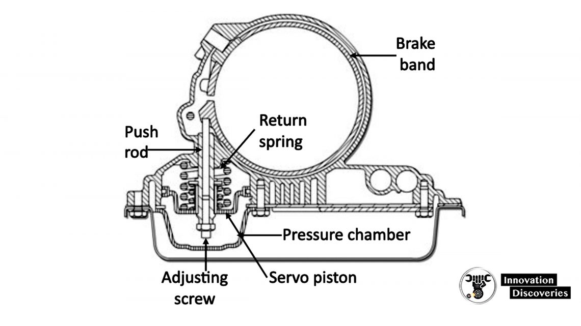
Servos are hydraulically operated. When a clutch has to be clamped, oil is routed to the servo that operates the band of the clutch.
Oil pressure pushes the servo piston away from its base, moving the pushrod that tightens the band, around the drum (the opposite end of the band is secured to the transmission case).
The band prevents one of the planetary gearset components from turning, allowing different gear ratios to be selected.
Return spring Push rod When the oil pressure is removed, the return spring moves the piston away to release the clamping force and allow the associated planetary gear component to rotate again.
The Hydraulics System
The hydraulics system is a complex maze of passages and tubes. It uses pressurized transmission fluid to control transmission and torque converter operations.
The fluid also cools and lubricates components.
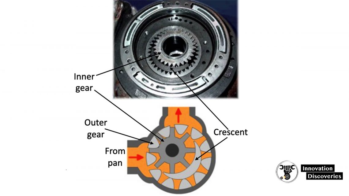
The Oil Pump provides a constant supply of pressurized fluid. It is directly connected to a flange on the torque converter housing and turns at engine speed.
The pump contains two gears. The inner gear, which is driven at engine speed, drives the outer gear.
Fluid is drawn up from the pan on one side of the crescent and forced into the hydraulic system on the other side.
The Hydraulics System
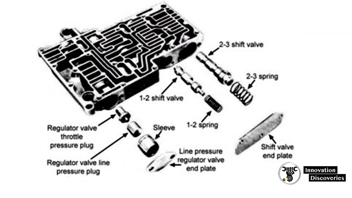
The Valve Body is responsible for distributing transmission fluid to control the transmission system.
It is constructed with a maze of channels and passages, and houses valves that activate clutch packs and band servos.
As each driving situation occurs, the valve body directs fluid to the required valve, to ensure smooth gear shifting takes place.
The valve body contains a manual valve, which is directly connected to the gear shift handle. It covers and uncovers various passages, depending upon the handle position.
The latest transmissions are controlled by computers, allowing precise gear shifting to take place. Some systems allow manual control of gear changes.
Bands, Clutches, and Gears
Typical examples of gear ratio selection, using bands, clutches and gears.
See More:
- 4 Common Symptoms of Automatic Transmission Problems
- How To Do Automatic Transmission Service Yourself?
- Automatic Transmission Valve Body Functions And Failure Symptoms
- Detecting 6 Common Automatic Transmission Problems
- Continuously Variable Transmission : Advantages and Disadvantages
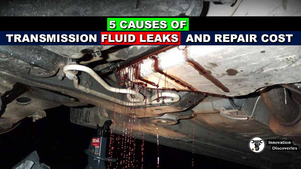
Read: 5 CAUSES OF TRANSMISSION FLUID LEAKS AND REPAIR COST
TORQUE CONVERTER: FUNCTIONS, PARTS, WORKING PRINCIPLES, AND TYPES
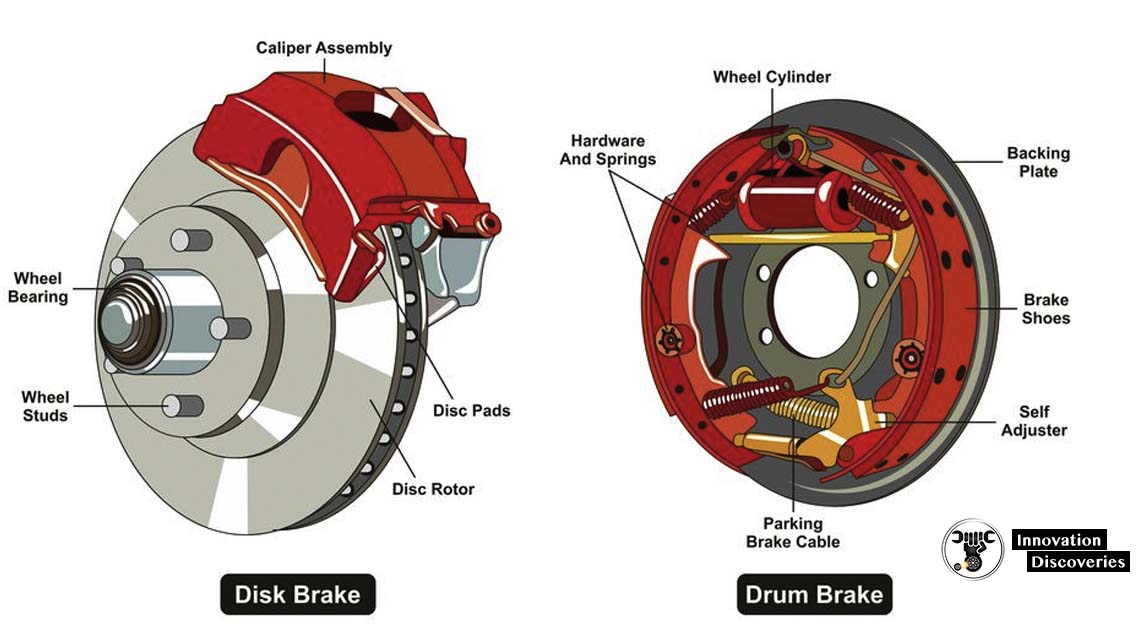
DIFFERENCE BETWEEN DRUM BRAKE AND DISC BRAKE
CONVERT DRUM BRAKES TO DISC BRAKES IN 3 STEPS!
WHAT’S THE DIFFERENCE BETWEEN BRAKE SHOES AND BRAKE PADS?
Read: HOW DOES AN OIL SUMP WORK IN YOUR CAR?
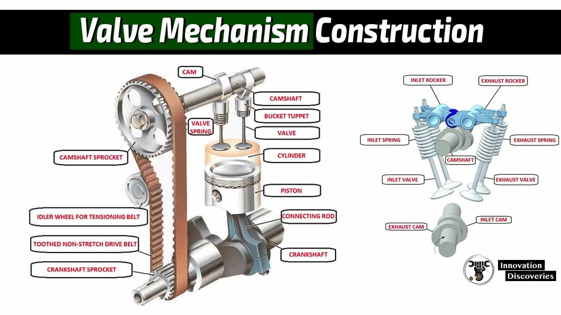
Download: VALVE SELECTION HANDBOOK | PDF